2.7 Definite-Time Overcurrent Protection (I>>, ANSI 50, 51, 67) with Direction Detection
49
7UM61 Manual
C53000-G1176-C127-3
Current Transform-
er in the Starpoint
(without direction
detection)
Example: Unit Connection
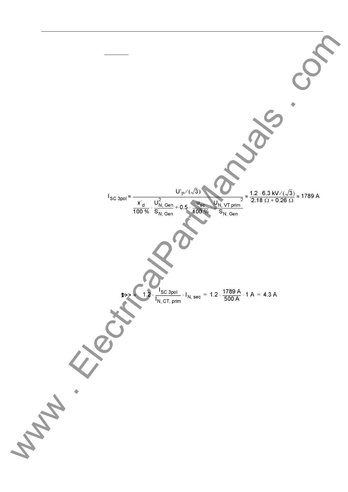
a) Short-circuit calculation
Three-pole short circuit
b) Setting value:
The setting value is achieved by means of a conversion on the secondary side. In
order to exclude an unwanted operation caused by overvoltages or transient phenom-
ena, an additional safety factor of about 1.2 to 1.3 is recommended.
A value of T I>> = 0.1 s is recommended as tripping time delay, in order to enable
preferred tripping of the differential protection.
Current Transform-
er on the Output
Side (with direction
detection)
If at Address 113 O/C PROT. I>> was configured as directional, the Addresses
1304 Phase Direction and 1305 LINE ANGLE are accessible. The inclination of
the direction straight line representing the separating line between the tripping and the
blocking zone can be adapted to the network conditions by way of the LINE ANGLE
parameter. To do this, the line angle of the network is set. The direction straight line is
perpendicular to the set direction angle. Together with the parameter 1304 Phase
Direction = Forward or Reverse, this parameter covers the entire impedance
level. This is the reverse direction, provided that the protective relay has been con-
nected correctly according to one of the diagrams in the Appendix. A small zone is
located between the forward and the reverse zone. Due to phase displacement angles
of the transformers, a proper direction decision is not possible. There is no tripping in
the configured preferential direction in this zone.
Rated apparent power - generator S
N, Mach
= 5.27 MVA
Rated voltage - generator U
N, Mach
= 6.3 kV
Direct-axis transient reactance x’
d
= 29 %
Transient synchronous generated voltage
(salient-pole generator)
U’
P
= 1.2 · U
N,Mach
Rated apparent power - transformer S
N, T
= 5.3 MVA
Rated voltage, on the generator side U
N, VT prim
= 6.3 kV
Transformer impedance u
sc
= 7 %
Current transformer I
N, CT, prim
= 500 A
I
N, sec
= 1 A
www . ElectricalPartManuals . com
 Loading...


