2.17 Circuit Breaker Failure Protection
269
7UT613/63x Manual
C53000-G1176-C160-2
Normally, the breaker will open and interrupt the fault current. The current monitoring
stage BF-I> quickly resets (typically
1
/
2
AC cycle) and stops the timer T-BF.
If the trip command is not executed (in case of breaker failure), current continues to
flow and the timer runs to its set limit. The breaker failure protection then issues a
command to trip the backup breakers which interrupt the fault current.
The reset time of the starting protection functions is not relevant because the breaker
failure protection itself recognises the interruption of the current.
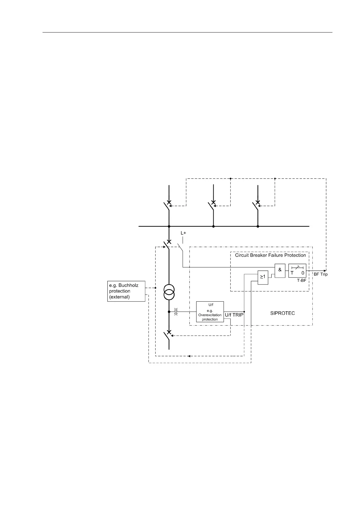
For protection relays where the tripping criterion is not dependent on current (e.g.
overexcitation protection or Buchholz protection), the current flow is not a reliable cri-
terion to determine the correct response of the circuit breaker. In such cases, the
circuit breaker position can be derived from the auxiliary contacts of the breaker or
from the feed-back information of the integrated control function. Therefore, instead of
monitoring the current, the condition of the circuit breaker auxiliary contacts are mon-
itored. (Figure 2-108).
Figure 2-108 Simplified function diagram of circuit breaker failure protection with current flow
monitoring
In 7UT613/63x both criteria, i.e. current flow and breaker position indication, are eval-
uated. If only one of the criteria is intended to be considered, this can be achieved by
corresponding configuration (Subsections 2.1.4).
Please make sure that the side or measuring location of the current and the monitored
circuit breaker belong together! Both must be located at the supply side of the protect-
ed object. In the simplified function diagram (figure 2-107) the current is measured at
the busbar side of the transformer (= supply side), therefore the circuit breaker at the
 Loading...


