3.1 Mounting and Connections
351
7UT613/63x Manual
C53000-G1176-C160-2
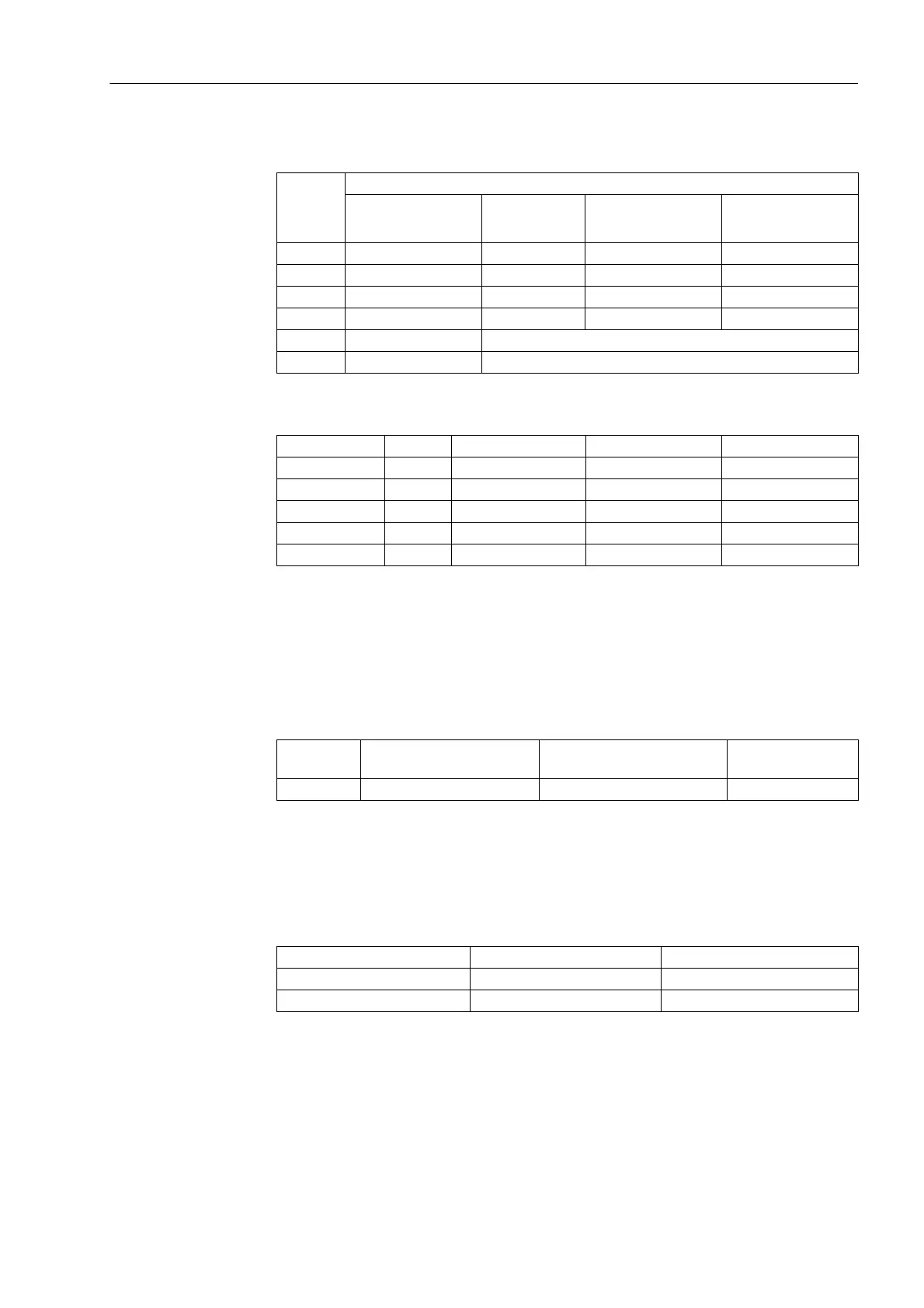
Table 3-2 Jumper settings of the rated voltage of the integrated Power Supply on the C-
CPU-2 processor board
Table 3-3 Jumper setting of the pickup voltages of the binary inputs BI1 to BI5 on the C-
CPU-2 processor module
1)
Factory settings for devices with rated power supply voltage 24 to 125 VDC
2)
Factory settings for devices with rated power supply voltage 110 to 250 VDC and 115 to 230
to 250 VAC
3)
Only for control voltage 200 VDC or 250 VDC
Table 3-4 Jumper setting of the quiescent state of the Life Contact on the processor
board C-CPU-2
By repositioning jumpers the interface RS485 can be modified into a RS232 interface
and vice versa.
Jumpers X105 to X110 must be set to the same position.
Table 3-5 Jumper settings of the integrated RS232/RS485 Interface on the C-CPU-2 pro-
cessor board
The jumpers are preset at the factory according to the configuration ordered.
With interface RS232 jumper X111 is needed to activate CTS which enables the com-
munication with the modem.
Jumper
Nominal voltage
24 to 48 VDC 60 to 125 VDC 110 to 250 VDC,
115 to 230 VAC
220 to 250 VDC,
115 to 230 VAC
X51 Not used 1-2 2-3 2-3
X52 Not used 1-2 and 3-4 2-3 2-3
X53 Not used 1-2 2-3 2-3
X55 Not used not used 1-2 1-2
Cannot be changed Interchangeable
Fuse T4H250V T2H250V
Binary Inputs Jumper Threshold 19 V
1)
Threshold 73 V
2)
Threshold 154 V
3)
BI1 X21 1-2 2-3 3-4
BI2 X22 1-2 2-3 3-4
BI3 X23 1-2 2-3 3-4
BI4 X24 1-2 2-3 3-4
BI5 X25 1-2 2-3 3-4
Jumper Open in the quiescent
state
Closed in the quiescent
state
Presetting
X40 1-2 2-3 2-3
Jumper RS232 RS485
X103 and X104 1-2 1-2
X105 to X110 1-2 2-3
 Loading...


