3 Mounting and Commissioning
352
7UT613/63x Manual
C53000-G1176-C160-2
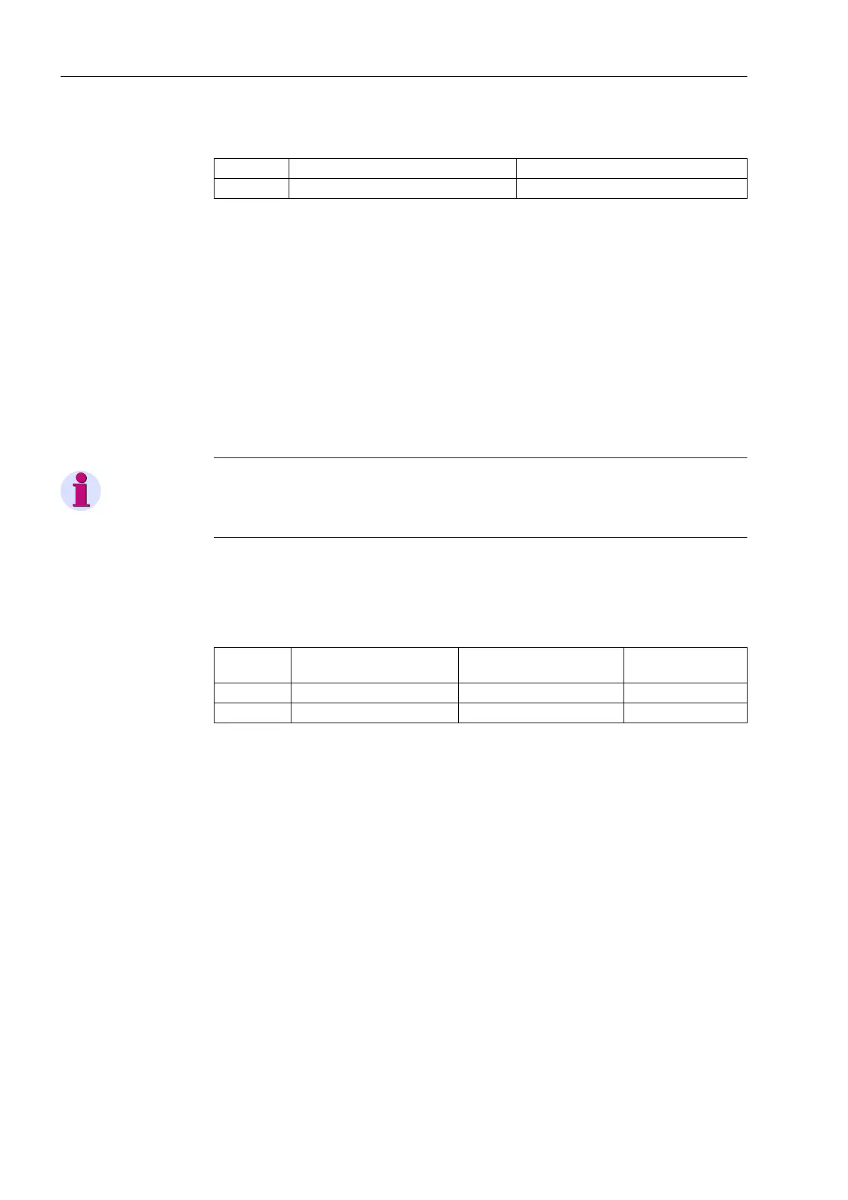
Table 3-6 Jumper setting for CTS (Clear To Send, flow control) on the C-CPU-2 proces-
sor board
1)
Delivery state
Jumper setting 2-3: The connection to the modem is usually established with a star
coupler or fibre-optic converter. Therefore the modem control signals according to
RS232 standard DIN 66020 are not available. Modem signals are not required since
the connection to the SIPROTEC 4 devices is always operated in the half-duplex
mode. Please use the connection cable with order number 7XV5100-4.
Jumper setting 1-2: This setting makes the modem signals available, i. e. for a direct
RS232-connection between the SIPROTEC 4 device and the modem this setting can
be selected optionally. We recommend to use a standard RS232 modem connection
cable (converter 9-pin to 25-pin).
Note
For a direct connection to DIGSI with interface RS232 jumper X111 must be plugged
in position 2-3.
If there are no external terminating resistors in the system, the last devices on a
RS485 bus must be configured via jumpers X103 and X104.
Table 3-7 Jumper settings of the Terminating Resistors of the RS485 interface on the
C-CPU-2 processor board
Note: Both jumpers must always be plugged in the same way!
When the device is delivered from the factory, the terminating resistors are discon-
nected (jumper setting 1-2).
The terminating resistors can also be connected externally (e.g. to the connection
module as illustrated in Figure 3-15). In that case the terminating resistors provided on
the C-CPU-2 processor board must be switched off.
Jumper X90 has no function. The factory setting is 1-2.
Jumper /CTS from interface RS232 /CTS triggered by /RTS
X111 1-2 2-3
1)
Jumper Terminating resistor
closed
Terminating resistor open Presetting
X103 2-3 1-2 1-2
X104 2-3 1-2 1-2
 Loading...


