3 Mounting and Commissioning
416
7UT613/63x Manual
C53000-G1176-C160-2
Caution!
For a turbine set, the intake of reverse power is only permissible for a short time, since
operation of the turbine without a certain throughput of steam (cooling effect) can lead
to overheating of the turbine blades!
• Adjust excitation until the reactive power amounts to approximately Q = 0. To check
this, read the active and reactive power including sign (negative) in the operational
measured values and note it down as P
0
(see table below). Read the reactive power
with sign in the operational measured values and note it down as Q
0
(see table
below).
• Slowly increase excitation to 30 % of rated apparent power of generator (overexcit-
ed).
– Read the motoring power P
1
with polarity (negative sign) in the operational mea-
sured values under and write it down (see figure below).
– Read out the reactive power Q
1
with polarity (positive sign) and write it down (see
table in the figure below).
• If possible reduce excitation to approximately 0.3 times rated apparent power of
generator (underexcited).
Caution!
Under-excitation may cause the generator fall out of step!
• Read the motoring power P
2
with polarity (negative sign) in the operational mea-
sured values under and write it down (see table 3-29).
– Read the reactive power Q
2
with polarity (negative sign) in the operational mea-
sured values and write it down (see table 3-29).
• Adjust generator to no-load excitation and shut down if applicable (if not, follow the
next margin heading).
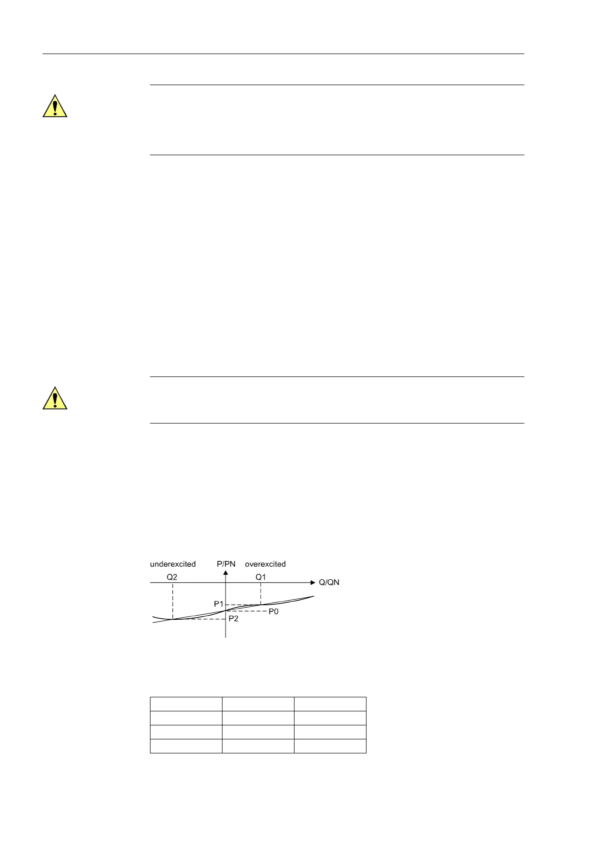
Figure 3-42 Determination of the correction angle ϕ
corr
Table 3-29 Motoring and reactive power for angle correction of the transformer error
State Motoring Energy Reactive Power
1P
0
Q
0
2P
1
Q
1
3P
2
Q
2
 Loading...


