Functions
2.8 Earth Fault Protection in Earthed Systems (optional)
SIPROTEC, 7SD5, Manual
C53000-G1176-C169-5, Release date 02.2011
227
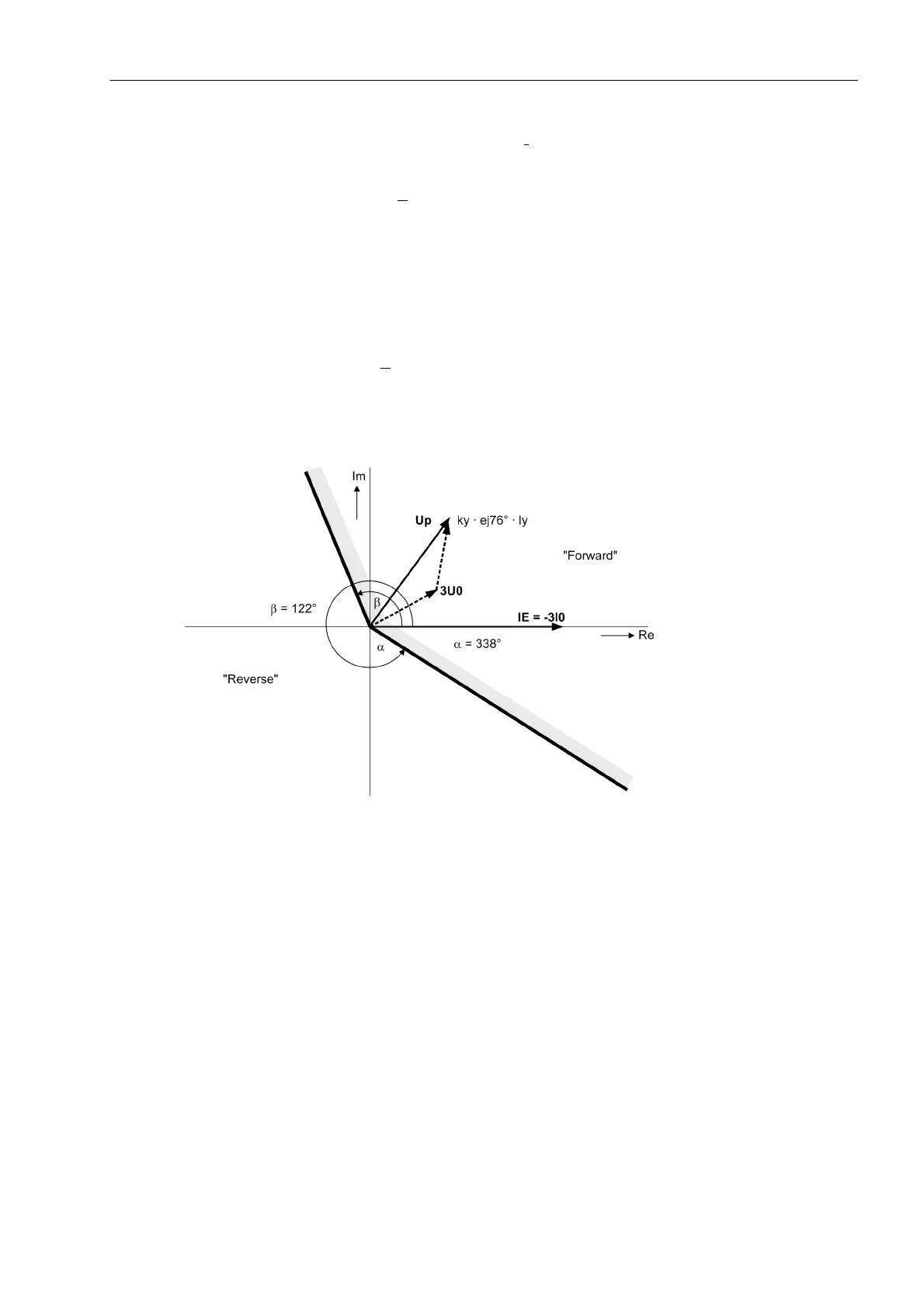
For the determination of direction, a minimum current 3I
0
and a minimum displacement voltage which can be
set as 3U0> are required. If the displacement voltage is too small, the direction can only be determined if it is
polarised with the transformer starpoint current and this exceeds a minimum value corresponding to the setting
IY>. Direction determination with 3U
0
is blocked if the device detects a fault condition in the voltage transformer
secondary circuit (binary input reports trip of the voltage transformer mcb, „Fuse Failure Monitor“, measured
voltage failure monitoring) or a single-pole dead time.
In order to allow directional determination also during a fault in the secondary circuit of the "normal" voltage
transformers, the broken delta winding U
en
can additionally be connected, in combination with a separate VT
miniature circuit breaker (address 210 U4 transformer = Udelta transf.). When this VT miniature circuit
breaker trips for the U
en
transformer (no. 362 „>FAIL:U4 VT“), the system switches automatically to the zero-
sequence voltage calculated from the "normal" voltage transformers.
Directional determination with 3·U
0
is possible as long as the calculated zero-sequence voltage is not disturbed
as well. The calculated zero-sequence voltage is deemed to be disturbed if the VT miniature circuit breaker has
tripped (binary input no. 361 „>FAIL:Feeder VT“), or if the "fuse failure monitor" or the measuring voltage
monitoring have picked up.
Figure 2-110 Directional characteristic of the earth fault protection
Determination of direction for long lines
In case of forward faults on very long lines, the zero-sequence voltage required for determination of direction
may become very small. The reason for this is the high ratio between the zero-sequence impedance of the line
and the infeed (source).
In the case of reverse faults, however, the zero-sequence voltage cannot drop that low if at the same time the
zero-sequence current exceeds the set pickup level; refer also to Figure 2-117.
For this reason, the system may automatically indicate a "forwards" direction when the zero-sequence voltage
drops below the threshold value 3186 3U0< forward.
 Loading...


