Functions
2.8 Earth Fault Protection in Earthed Systems (optional)
SIPROTEC, 7SD5, Manual
C53000-G1176-C169-5, Release date 02.2011
242
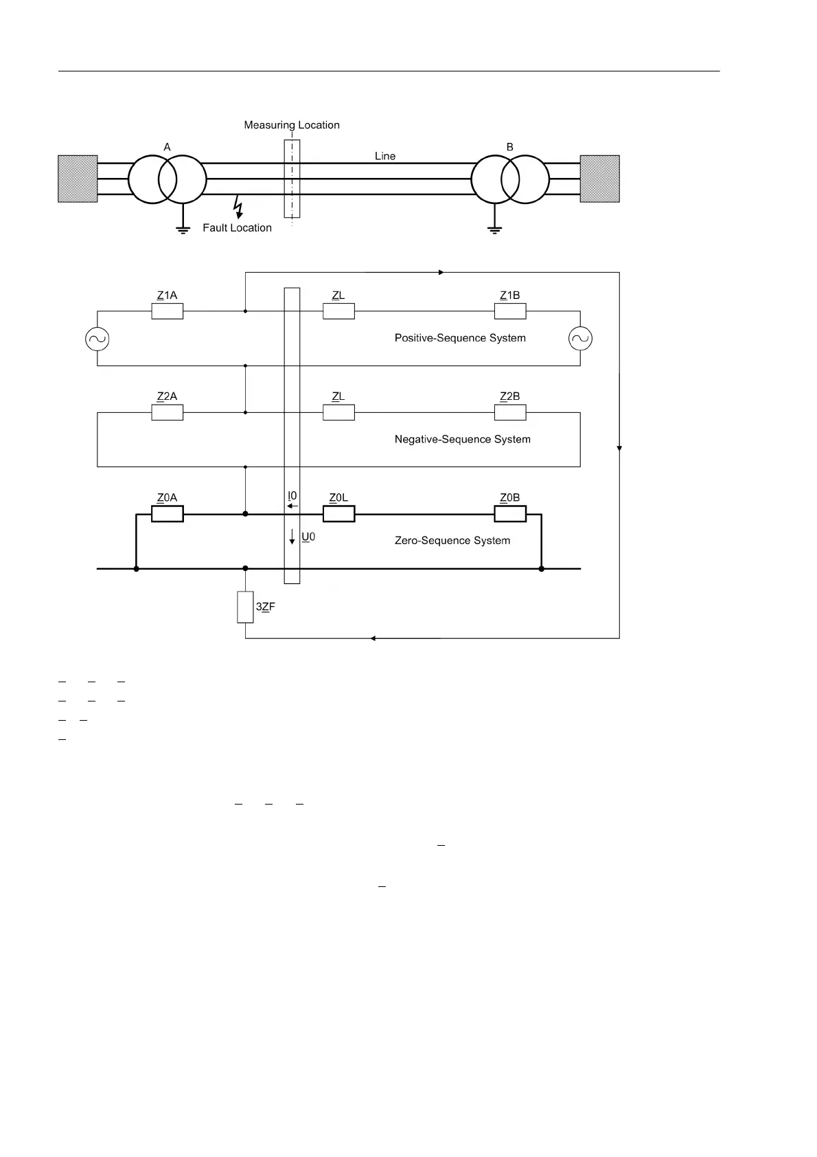
Figure 2-117 Power system diagram and symmetrical components for a single-pole earth fault in reverse direction
Z1A, Z2A, Z0A Source impedance side A, symmetrical components
Z
1B, Z2B, Z0B Source impedance side B, symmetrical components
Z
L, Z0L Line impedance, positive sequence and zero-sequence impedance
Z
F Fault impedance
For the protection of lines whose zero-sequence impedance is significantly higher than the infeed zero-se-
quence impedance (Z
0L
+ Z
0B
> Z
0A
in Figure 2-117), the following setting is recommended for parameter 3186
3U0< forward:
3U0< forward = 0,8 * 3I0>·(lowest directional stage)·* Z
0L
Additional safety can be obtained through the zero-sequence impedance of the infeed at the opposite line end,
which is not taken into account in the formula (Z
0B
in Figure 2-117).
In lines with series compensation, it is possible to compensate the negative influence of the series capacitor
on the directional determination of the earth fault protection. For this purpose, the reactance of the series ca-
pacitor must be entered in parameter 3187 XserCap. To prevent the compensation from falsifying the direction
measurement in case of reverse faults, the parameter 3187 XserCap must be set lower or equal to the zero-
sequence reactance of the line.
 Loading...


