Functions
2.1 General
SIPROTEC, 7SD5, Manual
C53000-G1176-C169-5, Release date 02.2011
39
Differential protection
The differential protection and the distance protection can each be configured as the main protection function.
If the differential protection is the main protection function of the device, DIFF.PROTECTION (address 112) is
set to Enabled. This also implies the supplementary functions of the differential protection such as breaker
intertrip.
For the communication of the protection signals to one or more device(s) each device is equipped with one or
two protection data interfaces (order option). The assignment of the protection data interfaces is essential for
the line protection system, i.e., the interaction of the devices at the ends of the protected object. Enable pro-
tection data interface 1 P. INTERFACE 1 in address 145, and protection data interface 2 (if available) P.
INTERFACE 2 in address 146, if you want to use them. At least one protection data interface is required to
use the differential protection function. A protected object with two ends requires at least one protection data
interface in each device. If there are more ends, it must be guaranteed that all devices that belong together are
interconnected directly or indirectly (via other devices). Section 2.2.1 Protection Data Topology provides more
information.
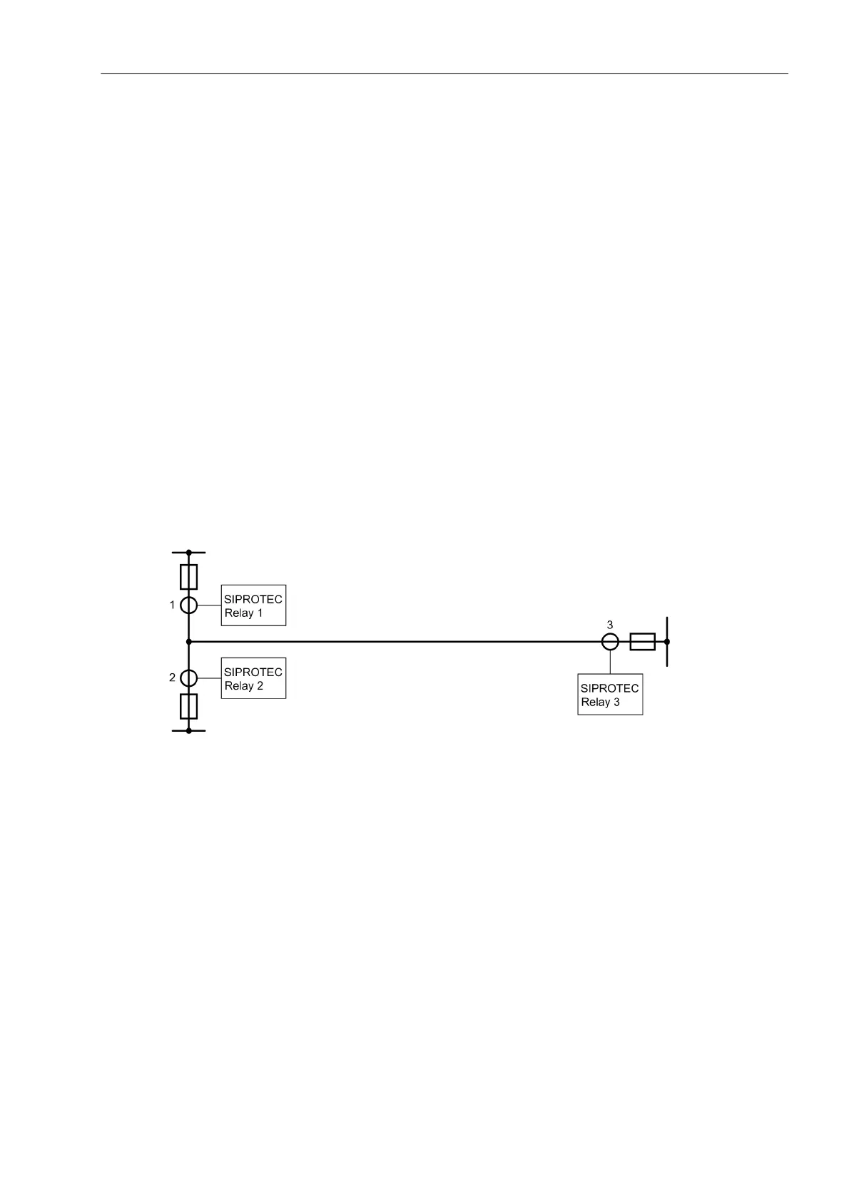
The number of devices (address 147 NUMBER OF RELAY) must match the number of the measuring points at
the borders of the object to be protected. Please observe that only current transformer sets that limit the pro-
tected object are counted. The line in Figure 2-1, for instance, has three measuring points and thus three
devices because it is limited by three current transformer sets. Two devices would normally be sufficient if
current transformers 1 and 2 are connected in parallel at the secondary side and connected to a device. How-
ever, in the event of an external fault causing a high short-circuit current to pass through the current transform-
ers 1 and 2, the restraint of the differential protection would be insufficient.
Figure 2-1 Protected object with 3 ends and 3 devices
If the device is connected to voltage transformers, this condition has to be set in address 144 V-
TRANSFORMER. The voltage dependent functions such as distance protection can only be used if voltage trans-
formers are connected.
If a power transformer is located in the protected zone, set this condition in address 143 TRANSFORMER (or-
dering option). The actual transformer data will be requested when the general protection data are set (see
Section 2.1.4.1 under margin heading „Topological Data for Transformers“ (optional)).
If you want to configure differential protection with charging current compensation, set this condition in address
149 charge I comp..

 Loading...


