Mounting and Commissioning
3.1 Mounting and Connections
SIPROTEC, 7SD5, Manual
C53000-G1176-C169-5, Release date 02.2011
498
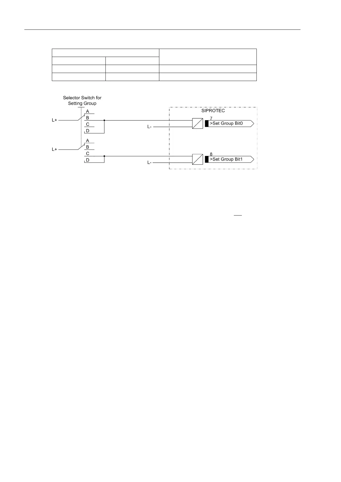
Figure 3-1 Connection diagram (example) for setting group switching with binary inputs
Trip Circuit Supervision
Please note that two binary inputs or one binary input and one bypass resistor R must be connected in series.
The pick-up threshold of the binary inputs must therefore be substantially below half the rated control DC volt-
age.
If two binary inputs are used for the trip circuit supervision, these binary inputs must be isolated, i.o.w. not be
communed with each other or with another binary input.
If one binary input is used, a bypass resistor R must be inserted (see following figure). The resistor R is con-
nected in series with the second circuit breaker auxiliary contact (Aux2) to allow the detection of a trip circuit
failure even when circuit breaker auxiliary contact (Aux1) is open and the command relay has dropped out. The
value of this resistor must be such that in the circuit breaker open condition (Aux1 is open and Aux2 is closed)
the circuit breaker trip coil (TC) is no longer picked up and binary input (BI1) is still picked up if the command
relay contact is open.
Not energized Energized Group C
Energized Energized Group D
Binary Input Active settings group
>Set Group Bit 0 >Set Group Bit 1
 Loading...


