Mounting and Commissioning
3.1 Mounting and Connections
SIPROTEC, 7SD5, Manual
C53000-G1176-C169-5, Release date 02.2011
499
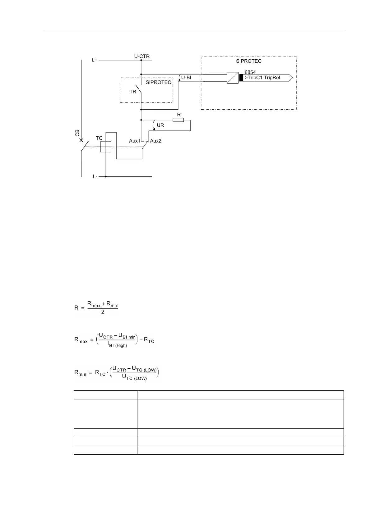
Figure 3-2 Principle of the trip circuit supervision with one binary input
TR Trip relay contact
CB Circuit breaker
TC Circuit breaker trip coil
Aux1 Circuit breaker auxiliary contact (NO contact)
Aux2 Circuit breaker auxiliary contact (NC contact)
U-CTR Control voltage for trip circuit
U-BI Input voltage of binary input
R Bypass resistor
UR Voltage across the bypass resistor
This results in an upper limit for the resistance dimension, R
max
, and a lower limit R
min
, from which the optimal
value of the arithmetic mean R should be selected:
In order that the minimum voltage for controlling the binary input is ensured, R
max
is derived as:
To keep the circuit breaker trip coil not energized in the above case, R
min
is derived as:
I
BI (HIGH)
Constant current with activated BI ( = 1.8 mA)
U
BI min
Minimum control voltage for BI
17 V for delivery setting for nominal voltages of 24/48/60 V;
73 V for delivery setting for nominal voltages of 110/125/220/250 V;
154 V for delivery setting for nominal voltages of 220/250 V
U
CTR
Control voltage for trip circuit
R
TC
DC resistance of circuit breaker trip coil
U
CBTC (LOW)
Maximum voltage on the circuit breaker trip coil that does not lead to tripping
 Loading...


