Functions
2.3 Differential Protection
SIPROTEC, 7SD5, Manual
C53000-G1176-C169-5, Release date 02.2011
94
Basic principle with multiple ends
For lines with three or more ends or for busbars, the principle of differential protection is extended in that the
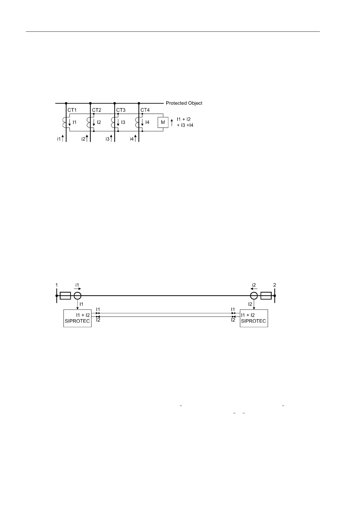
total sum of all currents flowing into the protected object is zero in healthy operation, whereas in case of a fault
the total sum is equal to the fault current (see Figure 2-23 as an example for four ends).
Figure 2-23 Basic principle of differential protection for four ends (single-phase illustration)
Transmission of measured values
If the entire protected object is located in one place — as is the case with generators, transformers, busbars
— the measured quantities can be processed immediately. This is different for lines where the protected zone
spans a certain distance from one substation to the other. To be able to process the measured quantities of all
line ends at each line end, these have to be transmitted in a suitable form. In this way, the tripping condition at
each line end can be checked and the respective local circuit breaker can be operated if necessary.
7SD5 transmits the measured quantities as digital telegrams via communication channels. For this, each
device is equipped with at least one protection data interface.
Figure 2-24 shows this for a line with two ends. Each device measures the local current and sends the infor-
mation on its intensity and phase relation to the opposite end. The interface for this communication between
protection devices is called protection data interface. As a result, the currents can be added up and processed
in each device.
Figure 2-24 Differential protection for a line with two ends
In case of more than two ends, a communication chain is built up by which each device is informed about the
total sum of the currents flowing into the protected object. Figure 2-25 shows an example for three ends. Ends
1 and 2 are derived from the arrangements of the current transformers shown on the left. Although this is ac-
tually only one line end, it should be treated in terms of differential protection as two ends because the current
is measured in two places. Line end 3 is situated on the opposite side.
Each device receives its corresponding local currents from the current transformers. Device 1 measures the
current i
1
and transmits its data as complex phasor I
1
to device 2. This device adds the share I
2
from its own
measured current i
2
and sends this partial sum to device 3. The partial sum I
1
+ I
2
finally reaches device 3 which
then adds its share I
3
. Vice versa, a corresponding chain leads from device 3 via device 2 to device 1. In this
way, the total sum of the three currents measured at the measuring points is available to all three devices.
The sequence of the devices in the communication chain need not correspond to the indexation, as shown in
Figure 2-25. The allocation is carried out during the parameterization of the topology, as explained in Section
2.2.1.

 Loading...


