10 SONOLINE G20 System Delivery Procedure
SONOLINE G20 US06-101.812.01.02.02 Siemens
10.04 sd
Page 10 of 26
Medical Solutions USA, Inc.
Power On the System 0
1. Attach the power cord safety lock to the system.
- Verify that the MAINS power switch is off.
- Choose the correct power cord and safety lock for the system (100V/115V or 230V).
NOTE
Two power cords and safety locks are provided; use only the ap-
propriate power cord and safety lock for the system.
• For 100 and 115V systems, use the white power cord (part num-
ber KP4819Y31AY3) with the small safety lock (part number
4H540092-0DB).
• For 230 V systems, use the gray power cord (part number
HG14A13V3.5M) with the large safety lock (part number
4H540070-0DB).
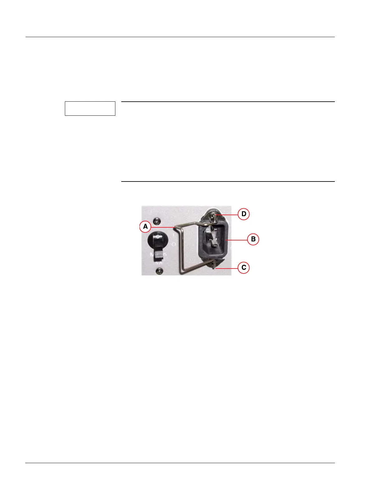
- Attach the safety lock to the system power inlet as shown in the figure below. Insert
the lower post of the safety lock first then the upper post.
Fig. 6: Power cord Safety Lock
Pos. A Safety lock
Pos. B Power inlet
Pos. C Lower post of the safety lock
Pos. D Upper post of the safety lock
- Position the safety lock on the left side of the power inlet; plug the power cord into the
power inlet.
- Press the safety lock on to the power cord; the safety lock must snap into the locking
position.
2. Plug the other end of the AC power cord into an approved power source.

 Loading...


