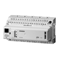
15 Electrical connections
15.1 Connection rules
CE- CE-
CE+ CE+ X1 X2 X3 X4 X5 X6 X8X7 GG
Q14
NPE
Q12
Pump
Low-voltage side
Mains voltage side
Konnex bus
Double terminal
with internal
connection
Auxiliary terminals
in the control panel
2-speed fan
Passive sensor /
signal source /
contact sensing
Active sensor /
signal source
Actuator
DC 0...10 V
T
erminal connection
c
oncept
Only 1 solid
wire or 1 stranded
wire can be connected to each terminal (cage
terminal).
Note
3140Z13
Connection p
rocedure
with spring cage
terminals
1. 2. 3.
1. Strip wire (length 7...8 mm; for module connector RMZ780: length 8…9 mm).
Steps
2. Connect wire using a screwdriver (size 0 to 1; for module connector: size 0).
3. Apply pressure with screwdriver while inserting the wire.
4. Remove screwdriver.
196 / 216
Siemens Switching and monitoring device RMS705B CE1P3124en
Building Technologies Electrical connections 01.04.2010

 Loading...


