20 – 1
20 Phase barriers
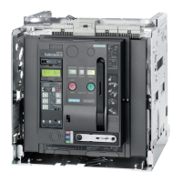
The rear sides of the fixed-mounted circuit breakers and drawout circuit-breaker cradles feature guide slots and mounting holes for the
purpose of incorporating phase barriers. The guide slots are not included on FS II class C breakers.
Usable material, e.g.:
NEMA GPO-3, min. thickness 2.3 mm (3/32“), max. thickness 4 mm (5/32”) or comparable material
(1) 8 mounting holes for self-tapping screw 4.2 mm, screw-in depth max. 16 mm
(2) Guide slot 4 mm wide

 Loading...