MDP 101-1
05.06.2020 Page 45
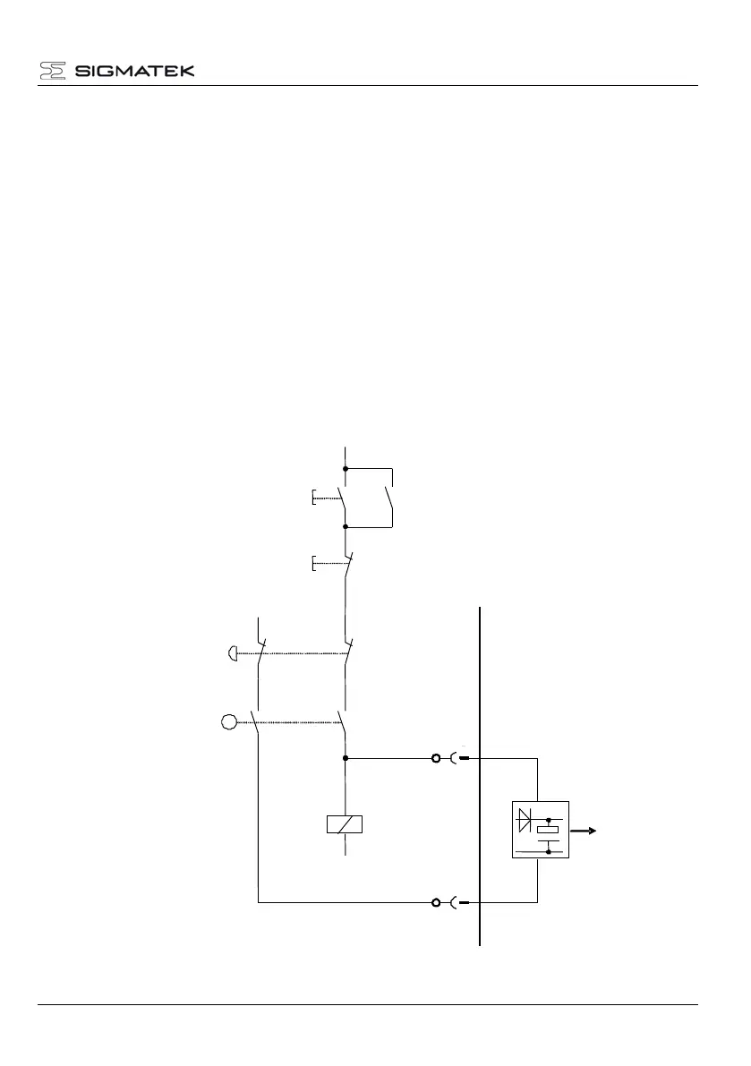
4.4 Example Connection with Switching Contacts
To meet the requirements of safety category 4, performance level "e" for EN 13849-1 and
SIL3 according to EN 62061, a two-channel control must be provided for the safety
functions.
The wiring for both connections must be provided with protective insulation (to avoid the
"external voltage supply" error).
For ENABLE_H this means, the other signals that can have a 24 V potential must be wired
separately.
For ENABLE_L this means, the other signals that can have "Ext. GND" potential must be
wired separately. Because the 24 V auxiliary voltage in the control cabinet is normally
grounded, caution must be taken to avoid a short-circuit with PE. The can occur through, for
example, wiring in a cable duct.
 Loading...