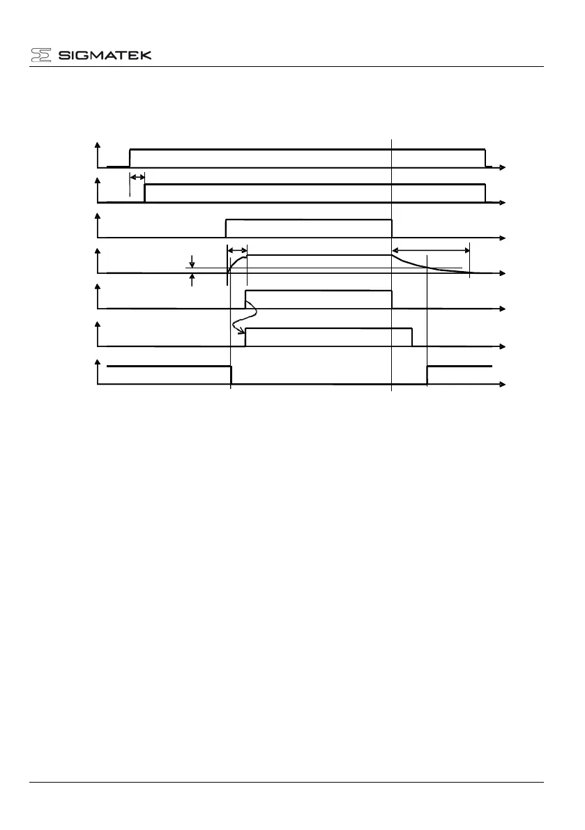
3.3.9 Turn on/off response of the servo amplifier
The turn on/off response of the servo amplifier is shown below.
5 seconds after turning on the 24 V auxiliary supply (start time of the micro controller), the
"Drive ready" signal is set to high.
The above image shows when the 24 V auxiliary supply activates the system through
turning on the main switch and the main supply is engaged later.
This, however, is not absolutely necessary. The main supply can also be activated with
the 24 V auxiliary supply at the same time.
Since the memory of the servo amplifier is volatile, received parameters must be stored in
the host controller. The advantage here lies in the automatic download of program data
when an amplifier is changed.
If the main supply is turned on, the capacitors in the intermediate circuit are charged. This
requires approximately 0.7 seconds.
If the main supply is turned off, the current of intermediate circuit is maintained and can
be used for controlled braking of the motor. If the motor is slowed, the energy is returned
to the intermediate circuit.
If the motor is stopped, the "enable" signal can be removed. After 7 minutes, the
intermediate circuit is discharged.
 Loading...