47
OPERATION AND ADJUSTMENTS
(Refer to the exploded views for key number
identification)
As strap is pulled from the dispenser, the dancer
arm swings forward to allow the coil to rotate
and pay-off the strap. The forward motion of the
dancer arm is gradually absorbed by a
compression spring (19) and the arm should stop
within an inch of contacting the forward stop
bumper (11). If, with a full coil of strap, the arm
impacts the bumper, increase the spring pressure
by turning the spring plunger (18) clockwise.
A nominal setting of the spring plunger will
result in it being positioned about 7/8" below the
top of the spring housing (14) when the arm is in
contact with the bumper (11).
If less tension is required, turn the plunger
counterclockwise but never loosen it beyond the
retaining screw (17).
As the arm swings back, a brake is applied to the
outer rim of the back disc assembly (7). The
brake should stop the coil from rotating. If the
coil is not stopped quickly enough and three or
four loose wraps of strap appear on the coil, the
brake will have to be adjusted.
To adjust the brake refer to the illustrations and
the steps below:
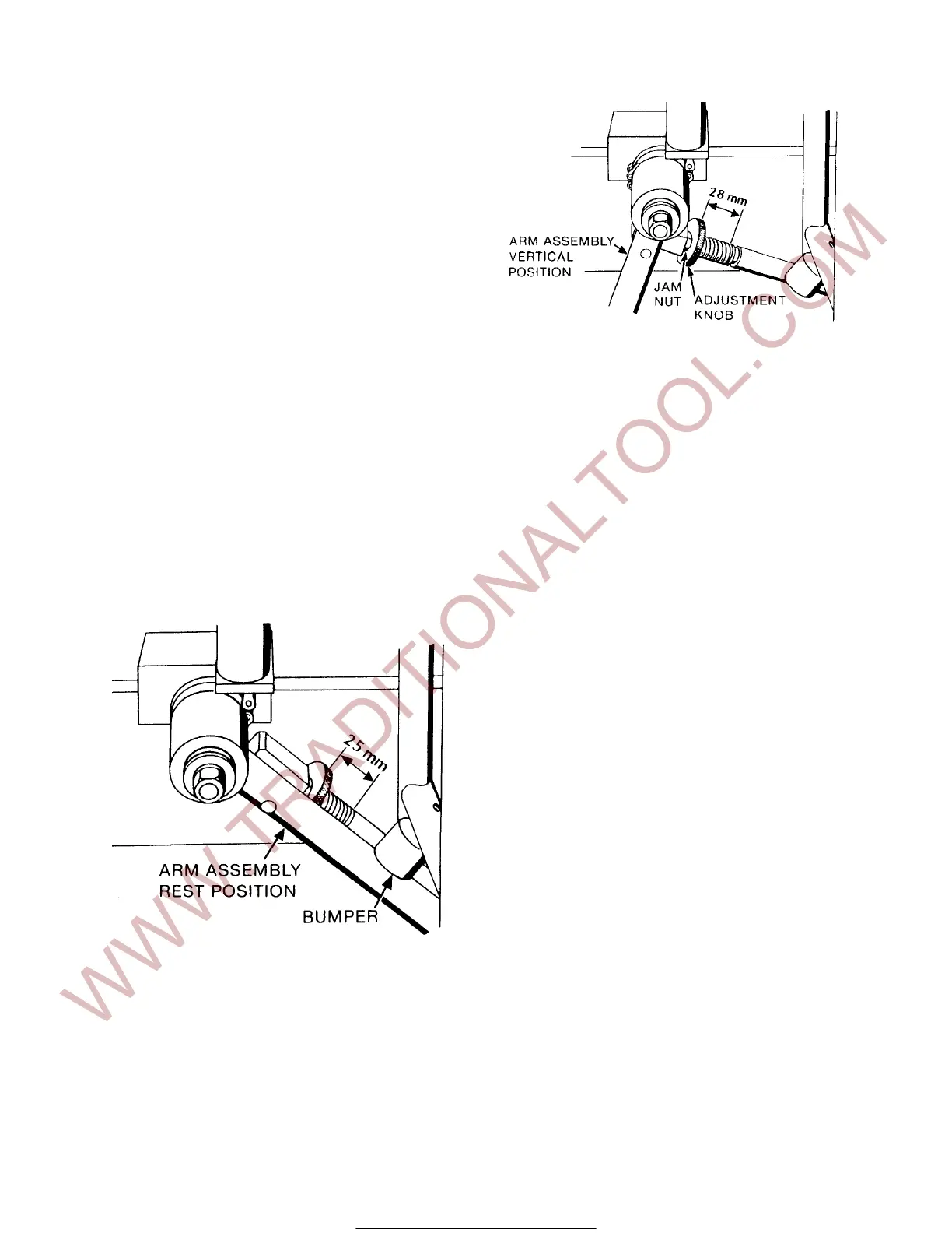
1. Hold the dancer arm assembly (24) in a
vertical position and measure the length of
the compression spring (33). The spring
should not be compressed with the dancer
arm vertical. The spring should measure 1
1/8" (28mm).
2. Loosen the set screw (31) in the knurled
adjustment knob (32) then loosen the jam
nut (30). This will allow the adjustment
knob (32) to be rotated.
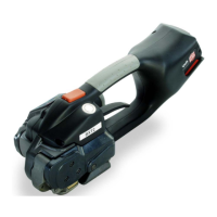
3. Move the dancer arm forward until it
contacts the bumper (11) and remeasure
the length of the compression spring (33).
It should measure 1" (25mm). If it measures
something other than 1", move the arm to
the vertical position and rotate the
adjustment knob in the direction needed to
obtain the 1" (25mm) dimension.
4. When set, tighten the jam nut (30) and the
set screw (31).
5. Note that the brake block (43) contacts the
outer flange with about fifty percent of the
length of the block. This means that the
block can be turned and reused in four
positions, greatly extending the life of the
block.
To properly position the block, place a
1/16" spacer between the lower part of the
block and the disc flange, then securely
tighten the mounting screw (42) and the
lock nut (45). Remove the spacer.
For Parts & Service 1-877-862-6699