AP10
Installation English
AP10 · Date 10.01.2020 · Art. No. 86832 · Mod. status 6/20
30
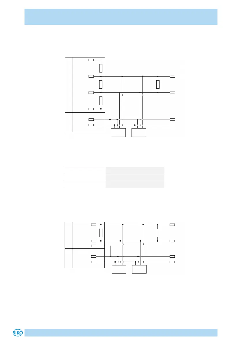
Connection diagram and level specification RS485
If termination and level specification do not occur in the bus master, they
must be carried out externally.
Node n
SGND
RS485-
RS485+
120 R
DÜA
DÜB
120 R
+5 V
470 R
470 R
0 V
24 V
24 V
0 V
Node 1
Bus-MasterPower supply
Fig. 4: Connection diagram and level specification RS485
Data transfer RS485 interface
RS485 baud rate max. bus network length
115.2kbit/s 200m
57.6kbit/s 400m
19.2kbit/s 1200m
Connection diagram CAN
A terminating resistor (120Ohm) is required for the fieldbus function, which
must be included at the last bus subscriber between CANH and CANL.
24 V
24 V
CAN_GND
CANL
CANH
120 R
CANH
CANL
Node 1
120 R
Node n
0 V
0 V
Bus-Master
Power supply
Fig. 5: Connection diagram CAN
 Loading...


