AP10
Installation English
AP10 · Date 10.01.2020 · Art. No. 86832 · Mod. status 6/20
31
Data transfer CAN interface
CAN baud rate max. bus network length
125kbit/s 320m
250bit/s 160m
500bit/s 80m
1Mbit/s 40m
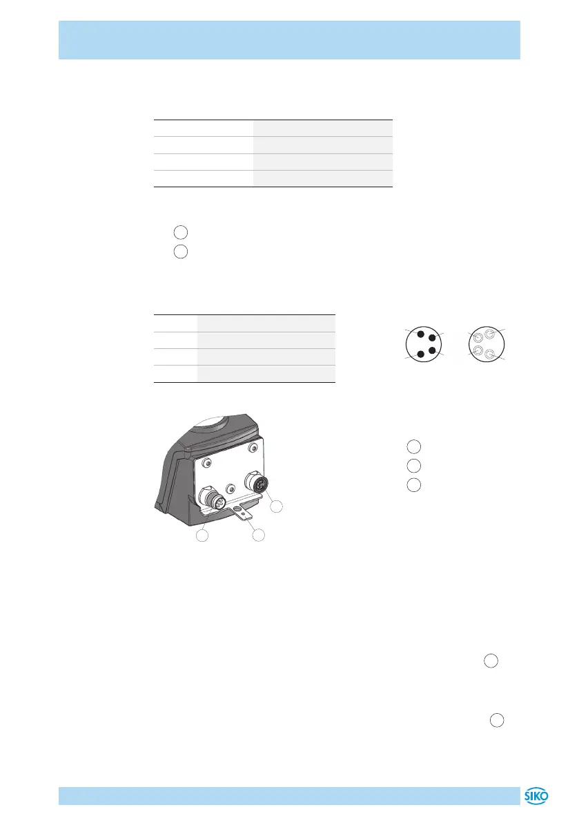
Pin assignment
•
1
Bus-IN: Pin 4 pin M8 (see Fig. 6).
•
2
Bus-OUT: Female 4 pin M8 (see Fig. 6).
For mating connector and cable extension accessories see chapter 8.
PIN Designation
1 DÜB/CANL
2 DÜA/CANH
3 +UB
4 GND
1
Bus-IN
2
Bus-OUT
3
Ground connection
2
3
1
Fig. 6: Pin assignment
Strand cross sections of lines 0.14 ... 0.5mm².
Ground connection
For protection against interference, the screens of the signal lines and the
power line must be connected on both sides. Potential dierences cause
inadmissible currents on the screen. Install the ground connection
3
onto the protective ground conductor potential between the plug con-
nectors (see Fig. 6). Use 6.3mm flat connectors or cable lug with short
strands 2.5 … 4mm² (not in the scope of delivery). For multiple position
indicators we recommend connecting the grounding to a ground bar
1
(see Fig. 7).
viewing side = plug-in side
Bus-OUTBus-IN
 Loading...


