AP10
Technical data English
AP10 · Date 10.01.2020 · Art. No. 86832 · Mod. status 6/20
40
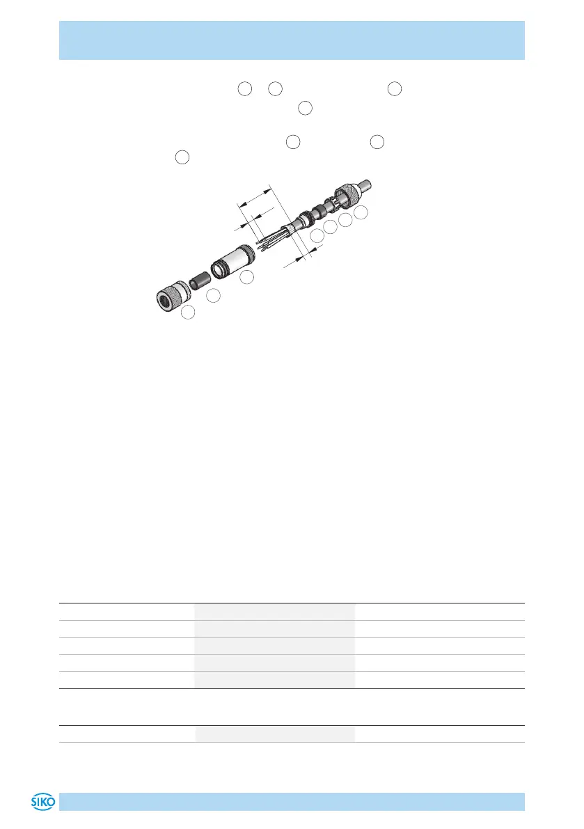
5. Mount parts
2
...
4
. Turn pressure screw
1
to secure the cable.
6. Thread insulating sleeve
6
, solder strands and mount insulating
sleeve.
7. Screw coupling sleeve
5
with element
7
and tighten pressure screw
1
.
Fig. 12: Straight matting connector M8
8.3 Mating connector M8 bus terminator (RS485, CANopen)
For the fieldbus to function, a terminating resistor is required (120Ohm).
• Accessory SIKO art. no. "BAS-0005" (pin 4 pin).
For multiple position indicators on one bus: connect terminating plug to
bus OUT of the last bus station (see chapter 4.2).
For one position indicator: connect terminating plug to bus OUT (see chap-
ter 4.2).
9 Technical data
Mechanical data Additional information
Shaft stainless special steel
Housing plastic, reinforced metallic connector thread
Color black, RAL 9005
Speed ≤500rpm
Weight ~0.2kg
Electrical data Additional information
Operating voltage 24VDC ±20%
 Loading...


