AP10
Commissioning English
AP10 · Date 10.01.2020 · Art. No. 86832 · Mod. status 6/20
33
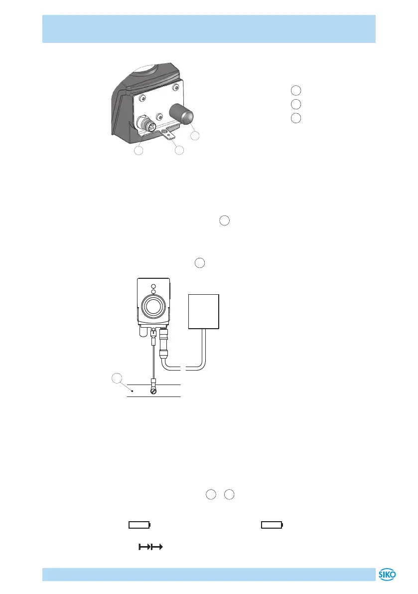
1
IO-Link
2
Ground connection
3
Dust cap
2
1
3
Fig. 8: Pin assignment
Strand cross sections of lines 0.14 ... 0.5mm².
Ground connection
Install the ground connection
2
onto the protective ground conductor
potential next to the plug connector (see Fig. 8). Use 6.3mm flat con-
nectors or cable lug with short strands 2.5 … 4mm² (not in the scope of
delivery). For multiple position indicators we recommend connecting the
ground to a ground bar
1
(see Fig. 9).
IO-Link
Master
1
Fig. 9: Ground bar
5 Commissioning
Display and control keys
The position indicator has a two-line display with special characters and
three control keys. The keys serve for position indicator parameteriza-
tion and control. The LEDs
1
+
2
serves for positioning monitoring. In
the basic state (factory setting), the 1st line displays the actual value
and the 2nd line the set point. With a critical battery status, the special
sign blinks, with an empty battery, glows permanently. With
incremental measurement switched on, the incremental measurement
symbol is displayed.
 Loading...


