AP10
Commissioning English
AP10 · Date 10.01.2020 · Art. No. 86832 · Mod. status 6/20
34
1 2
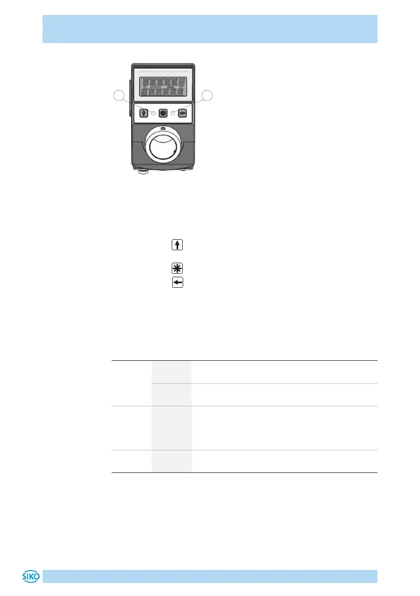
Fig. 10: Operating elements
Manual setup operation
After applying supply voltage (see chapter 4.2), the position indicator will
be on the uppermost level of the menu structure (default/delivery state).
• Pressing the key enables or disables the incremental measurement
function.
• Pressing the key starts calibration (see User manual).
• Pressing the key starts the configuration mode (see User manual).
LED displays
In the basic state (factory setting), the LED display has the following
meaning.
Color State Description
both LED
green
on Actual position value is within the programmed
position window.
o Actual position value is outside the programmed
position window.
one LED
red
on Actual position value is outside the programmed
position window. The red LED indicates the direc-
tion of shaft rotation required to arrive at the set-
point.
both LED
red
o Actual position value is within the programmed
position window.
Configuration
The required parameters are set in the configuration mode. On the 1st line
of the display, the parameter will be shown and on the 2nd line the res-
pective value will be displayed.
 Loading...


