AP10
Installation English
AP10 · Date 10.01.2020 · Art. No. 86832 · Mod. status 6/20
32
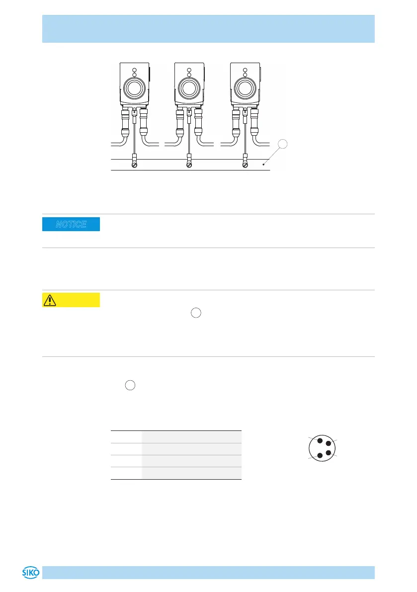
Fig. 7: Ground bar
Admissible power input
Supply for the position indicator shall be sized suciently. Current draw is
temporarily higher than nominal current at the moment of switching on.
For the supply value refer to the technical data in chapter 9.
4.4 Connection concept (IO-Link)
Position indicator failure
Removing the dust cap
3
and opening the screw results in loss of the pro-
tection type.
` Do not remove dust cap.
` Do not open the screw.
Pin assignment
•
1
IO-Link: Pin 4 pin M8 (see Fig. 8).
For mating connector and cable extension accessories see chapter 8.
PIN Designation
1 L+ (+UB)
2 nc
3 L- (GND)
4 C/Q
NOTICE
CAUTION
4
2
viewing side = plug-in side
 Loading...


