AP10
Installation Deutsch
AP10 · Datum 10.01.2020 · Art. Nr. 86832 · Änd. Stand 6/20
7
Ausfall Positionsanzeige
` IP-Schutzart bei Montage beachten (siehe Kapitel 9), bei Bedarf
schützen.
` Positionsanzeige nicht selbst önen (Ausnahme siehe Kapitel 6).
` Schläge auf das Gerät vermeiden.
` Keinerlei Veränderung am Gerät vornehmen.
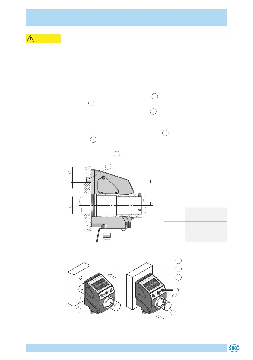
Vorbereitung Montage (Abb. 1, Abb. 2, Abb. 3):
1. Bohrung ød für Drehmomentstütze
1
auf Abstand L1 zur Antriebs-
welle
2
fertigen.
2. Durchmesser øD der Antriebswelle
2
beachten.
Montage (Abb. 1, Abb. 2, Abb. 3):
1. Positionsanzeige bis Anschlag auf Welle
2
schieben. Drehmoment-
stütze
1
in vorhandene Bohrung einführen (verspannungsfreie Mon-
tage). Ein Langloch für die Drehmomentstütze wird empfohlen.
2. Gewindestifte M3
3
mit maximal 0.2Nm anziehen.
Maß ød ø6
H8
(Form A)
ø10
+0.8
(Form B)
Maß L1 22 oder 30
(±0.1 bei Form A)
Maß øD ø20
(Spielpassung)
Tab. 1: Einbaumaße
Abb. 1: Einbaumaße
Abb. 2: Montage
Abb. 3: Anzugsmoment
Gewindestift
1
Drehmomentstütze
2
Welle
3
Gewindestift
VORSICHT
 Loading...


