BRAVO MAXIMA II Operating manual - English
12 Copyright Silca 2011
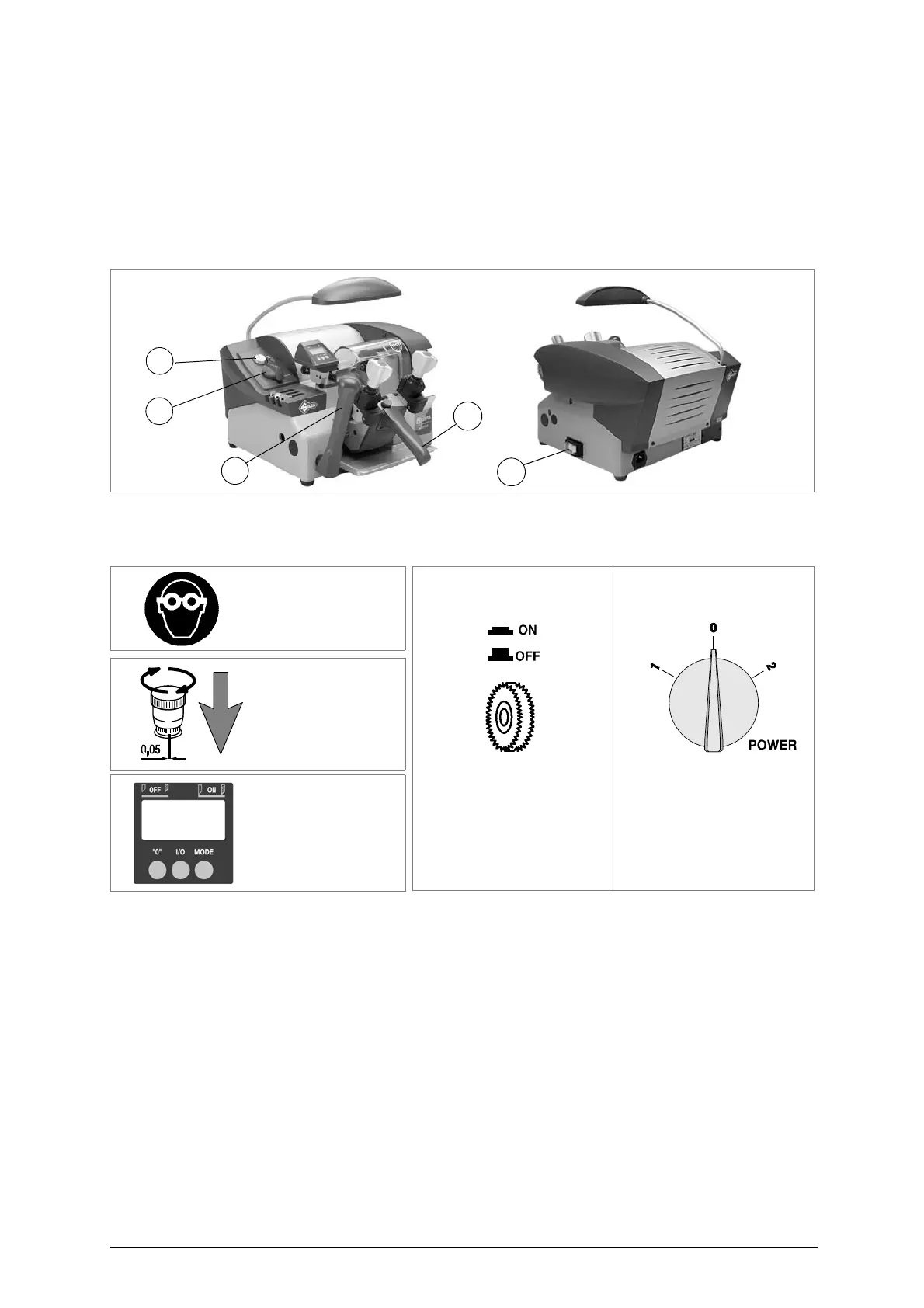
5.4 Description of work station
The key-cutting machine needs only one operator, who has the following controls at his/her disposal:
• master switch (C)
• commutator (P)
• push button (M) to activate the brush
• carriage movement lever (L), placed at the bottom left-hand side
• carriage handle (V)
Fig. 9
5.5 Graphics
5.6 Separate parts
The separately packed parts must be installed on the BRAVO MAXIMA key-cutting machine by the
purchaser, as follows:
Connection wire
Connect the supply wire to the inlet on the back of the machine.
5.7 Connection to the mains
For the safety of the operator and the machine it is important to ensure that the machine is connected
to the proper mains voltage by means of an earthed differential switch.
THE USE OF
PROTECTIVE GOGGLES
IS COMPULSORY
BRUSH PUSH BUTTON
MOTOR START-UP
COMMUTATOR
2 SPEED
(OFF)
(speed 1) (speed 2)
TRACER POINT
WITH MICROMETRIC
REGULATION