Smart Machine Smart Decision
SIM868_Series_Hardware_Design_V1.06 24 2017-07-13
5. Application Interface of GSM
5.1. Power Supply of GSM
The recommended typical power supply voltage of GSM is 4.0V, and range from 3.4V to 4.4V. The maximum
current consumption of GSM can reach 2A maximum during a transmitting burst period, which will cause a big
voltage drop on the GSM_V BAT. So, to decrease the voltage drop, it is necessary to add an additional circuit at
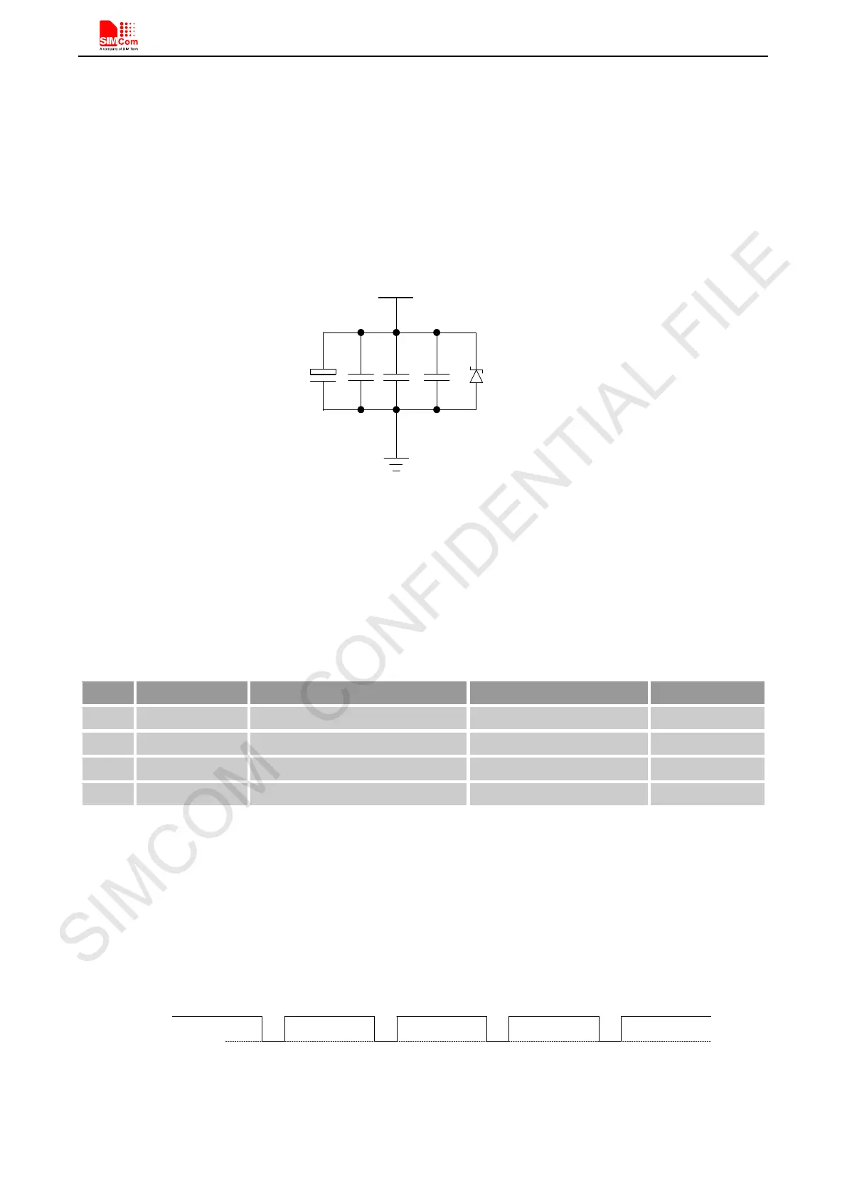
the GSM_V BAT pin, which is illustrated in Figure 8.
GSM_VBAT
5.1V
500mW
C
A
C
B
33pF
10pF
Figure 8: Reference circuit of the GSM_VBAT input
For the GSM_VBAT input, a 100uF tantalum capacitor
C
A
(low ESR) and a 1uF~10uF ceramics capacitor C
B
are strongly recommended. Add the 33pF and 10pF capacitors can effectively eliminate the high frequency
interference. A 5.1V/500mW zener diode is strongly recommended, which can prevent chip from damaging by
the voltage surge. These capacitors and zener diode should be placed as close as possible to GSM_V BAT p in.
Table 7: Recommended zener diode
Vendor Part number Power(watts) Packages
1 On semi MMSZ5231BT1G 500mW SOD123
3 Vishay MMSZ4689-V 500mW SOD123
When designing the power supply circuit in customers’ application, pay special attention to power loss. Ensure
that the input GSM_VB AT voltage never drops below 3.0V even when current consumption rises to 2A in the
transmit burst. If the GSM_V BAT voltage drops below 3.0V, the GSM may be shut off automatically. The PCB
traces from the GSM_VBAT pin to the power supply must be wide enough (at least 60mil) to decrease voltage
drops in the transmit burst. The power IC and the bypass capacitor should be placed to the GSM_VB AT as close
as possible.
Figure 9: The minimal GSM_VBAT voltage requirement at GSM_VBAT drop