Smart Machine Smart Decision
SIM868_Series_Hardware_Design_V1.06 34 2017-07-13
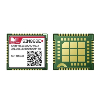
The behavior of the RI pin is shown in the following figure when the module is used as a receiver.
HIGH
LOW
Idle Ring
Hang up the call
Establish the call
RI
Figure 25: UART1_RI behaviour of voice calling as a receiver
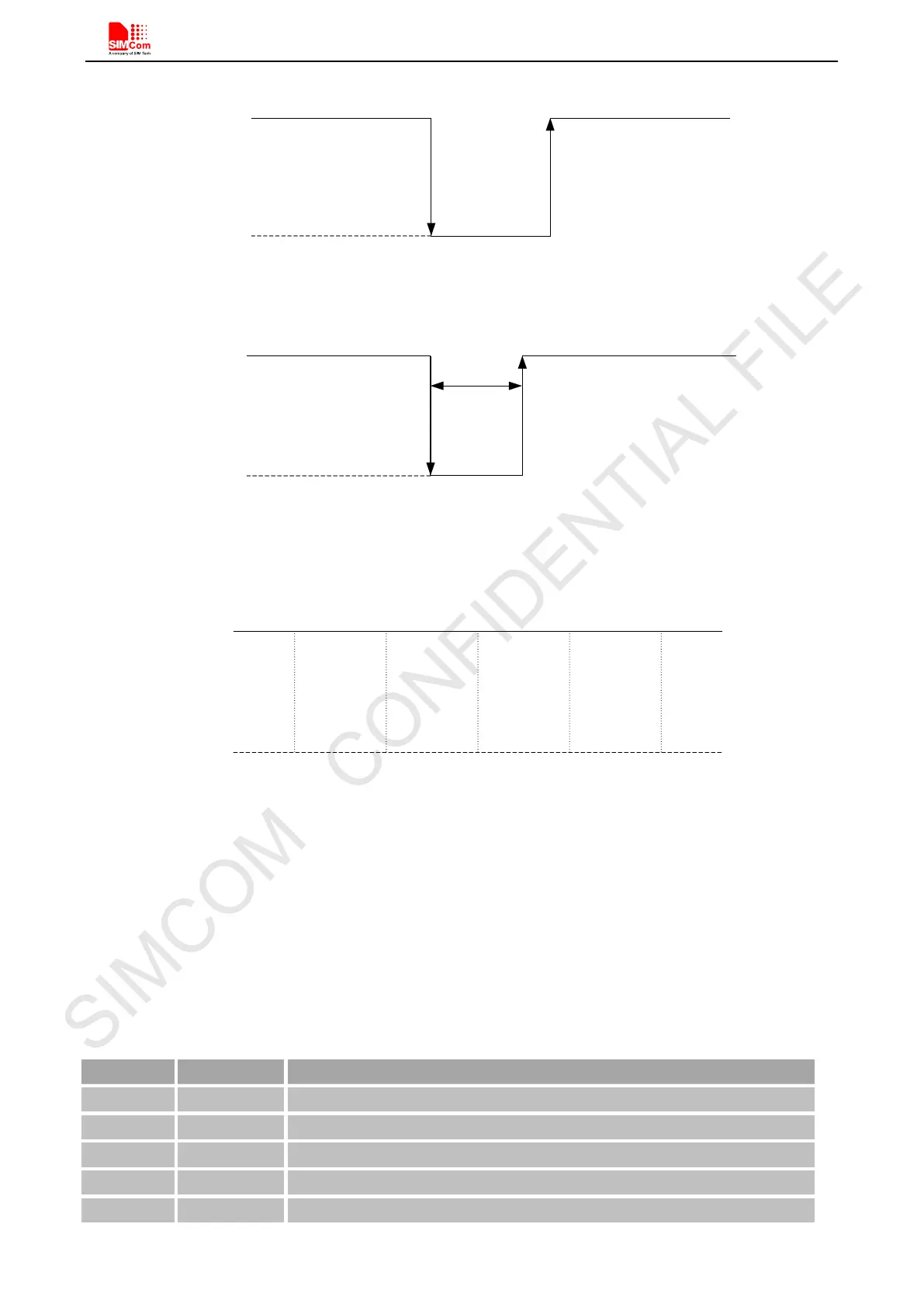
HIGH
LOW
Idle
RI
120ms
Receive SMS
URC
Figure 26: UART1_RI behaviour of URC or receive SMS
However, if the module is used as caller, the UART1_RI will remain high. Please refer to Figure 27.
HIGH
LOW
Idle
Ring
Establish
the call
Hang up
the call
Idle
RI
Figure 27: UART1_RI behaviour as a caller
5.7. Audio Interfaces
GSM part provides an analog input (MICP; MICN), which could be connected to electric microphone. The
module also provides two analog audio outputs (SPK1P/1N; SPK2P/2N).
Table 13: Audio interface definition
Pin name Pin number Function
MICP 9 Audio input positive
SPK1P 11 Audio output positive
SPK2P 44 Audio output positive