Smart Machine Smart Decision
SIM868_Series_Hardware_Design_V1.06 51 2017-07-13
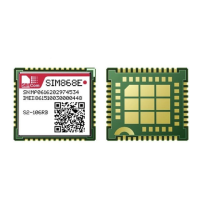
Module
1PPS
GPS_VBAT
4.7K
47K
R
Figure 48: 1PPS Application circuit
6.8. Antenna Interface
Antenna interface of GNSS:
The input impendence of the antenna should be 50Ω, and the VSWR should be less than 2.
It is recommended that the GNSS antenna should be placed as far as possible to other antenna.
The isolation of the antenna should be more than 30dB
Note
:
About RF design, please refer to document [15], [16] for more information.
6.8.1. Passive Antenna
Passive antenna contains only the radiating element, e.g.: the ceramic patch, the helix structure, and chip antennas.
Sometimes it also contains a passive matching network to match the electrical connection to 50Ω impedance.
The most common antenna type for GPS/GLONASS application is the patch antenna. Patch antennas are flat, gen
erally have a ceramic and metal body and are mounted on a metal base plate.
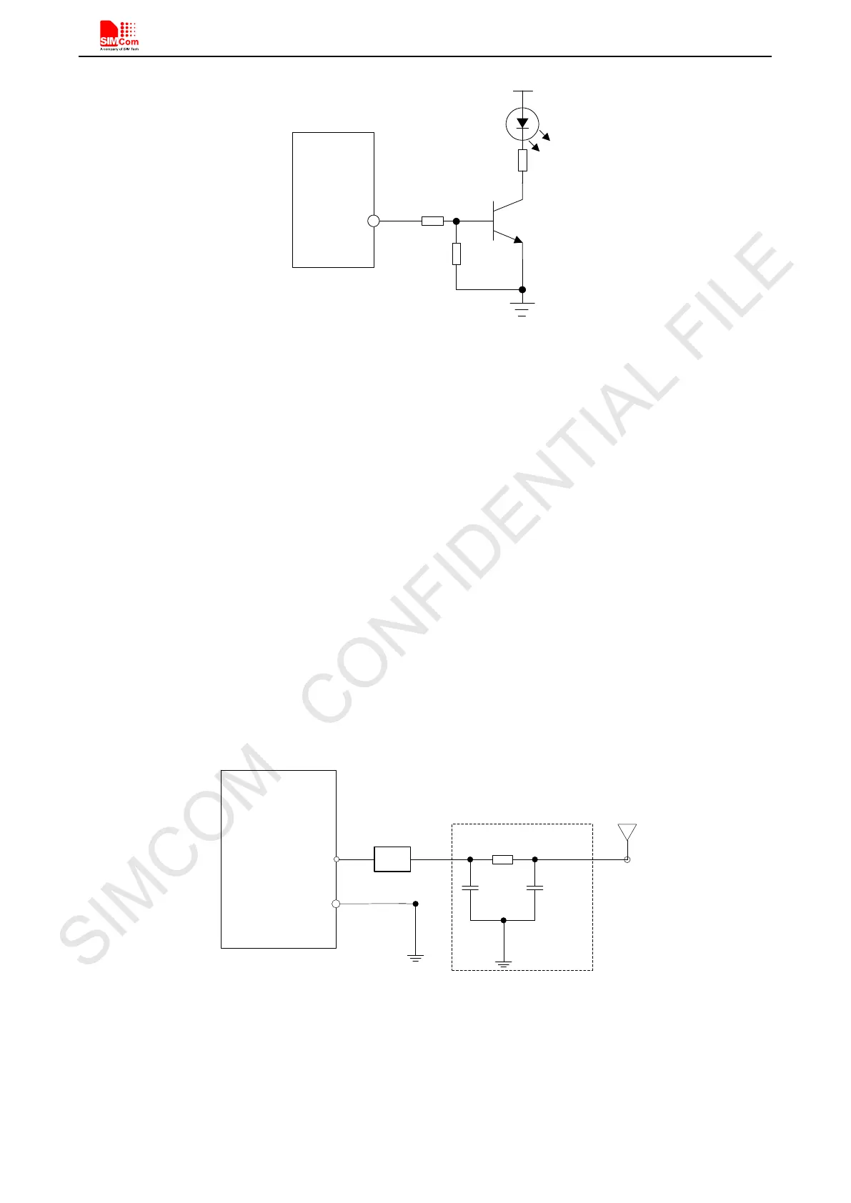
C101
MODULE
GPS_ANT
GND
C102
R101
Matching circuit
GNSS
Passive
Antenna
(PIN68)
(PIN67)
BPF
Figure 49: GNSS passive antenna matching circuit
The components R101, C101 and C102 are used for antenna matching, the BPF is used for out of band noise
signal suppression. The components’ value only can be got after the antenna tuning. Normally R101 is 0Ω, C101
and C102 are not mounted.