Smart Machine Smart Decision
SIM868_Series_Hardware_Design_V1.06 36 2017-07-13
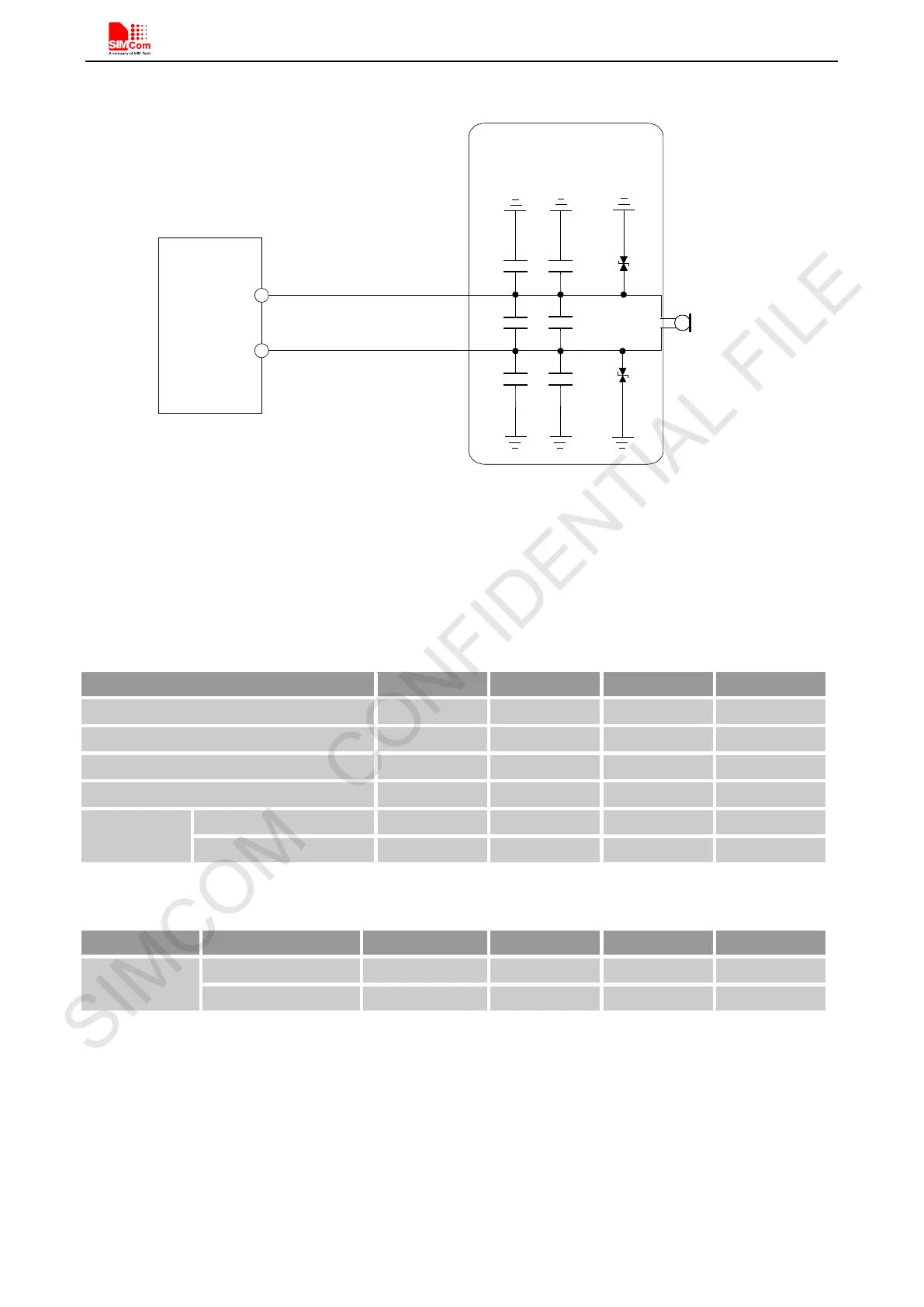
5.7.2. Microphone Interfaces Configuration
Electret
Microphone
The lines in bold type should
be accorded to differential
signal layout rules
These components should
be placed to microphone
as close as possible
MICP
Module
MICN
ESD
ESD
10pF
33pF
33pF
33pF
10pF
10pF
Figure 29: Microphone reference circuit
5.7.3. Audio Electronic Characteristic
Table 15: Microphone input characteristics
Parameter Min Typ Max Unit
Microphone biasing voltage - 1.9 2.2 V
Working current - - 2.0 mA
Input impedance(differential) 13 20 27 KΩ
Idle channel noise - - -67 dBm0
SINAD
Input level:0dBm0 - 69 - dB
Table 16: Audio output characteristics
Parameter Conditions Min Typ Max Unit
Normal output
R
L
=32 Ω receiver - 15 90 mW
5.7.4. TDD Noise of GSM
Audio signal could be interfered by RF signal. Coupling noise could be filtered by adding 33pF and 10pF
capacitor to audio lines. 33pF capacitor could eliminate noise from GSM850/EGSM900MHz, while 10pF
capacitor could eliminate noise from DCS1800/PCS1900Mhz frequency. Customer should adjust this filter
solution according to field test result.