Smart Machine Smart Decision
SIM868_Series_Hardware_Design_V1.06 41 2017-07-13
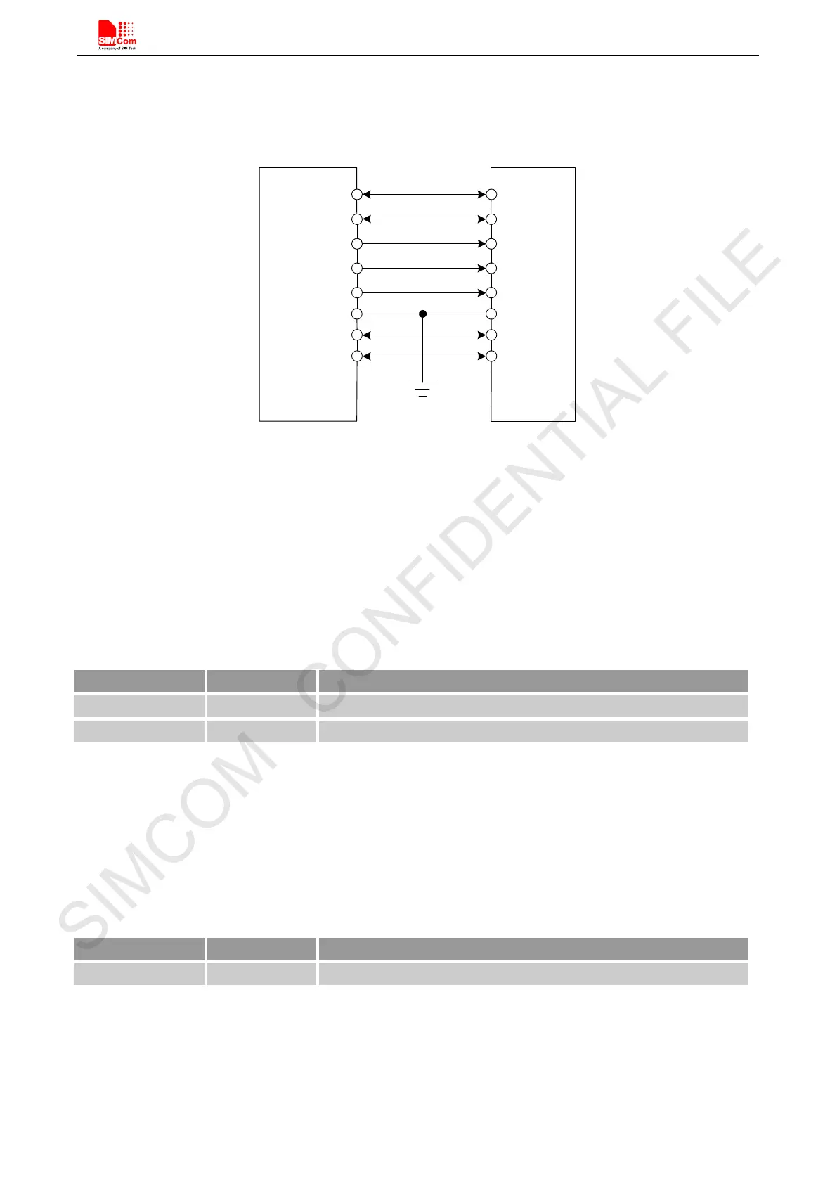
5.9. SD Interface
The reference circuit is recommended in Figure 34:
Module
SD
GND
DAT2
DAT3
CMD
VDD
CLK
DAT0
DAT1
MCCA2
MCCA3
MCCM0
VDD_SD
MCCK
GND
MCCA0
MCCA1
Figure 34: SD reference circuit
If the power supply is 2.8V for SD card, customer can use VDD_EXT; if the power supply is 3.3V, please use
external LDO.
5.10. I2C Bus
The SIM868 provides an I2C interface which is only used in the embedded AT application.
Table 20: Pin definition of the I2C
Note:
1. I2C should be pulled up to 2.8V via 4.7K resistor externally.
2. I2C function is not supported in the standard firmware. If you need, please contact SIMCom.
5.11. ADC
Table 21: Pin definition of the ADC
SIM868 provides an auxiliary ADC, which can be used to measure the voltage. Customer can use AT command
“AT+CADC” to read the voltage value.
Note: Customer can use AT command set mode. For details, please refer to document [1].
Pin name Pin number Description
SCL 65 I2C serial bus clock(open drain output)
I2C serial bus data(open drain output)