Smart Machine Smart Decision
SIM800C_Hardware_Design_V1.02 17 2015-4-27
4. Application Interface
4.1. Power Supply
The power supply range of SIM800C is from 3.4V to 4.4V. Recommended voltage is 4.0V. The transmitting
burst will cause voltage drop and the power supply must be able to provide sufficient current up to 2A. For the
VBAT input, a bypass capacitor (low ESR) such as a 100 µF is strongly recommended.
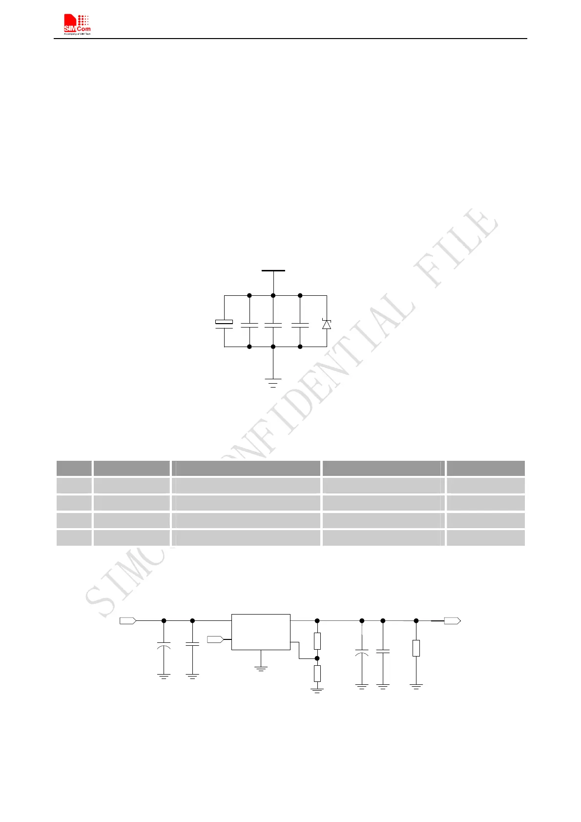
For the VBAT input, a 100uF Tantalum capacitor (C
A low ESR) and a 1uF~10uF Ceramics capacitor CB are
strongly recommended. Increase the 33pF and 10pF capacitors can effectively eliminate the high frequency
interference. A 5.1V/500mW Zener diode is strongly recommended, the diode can prevent chip from damaging
by the voltage surge. These capacitors and Zener diode should be placed as close as possible to SIM800C
VBAT pins.
VBAT
5.1V
500m W
C
A
C
B
33pF 10pF
Figure 5: Reference circuit of the VBAT input
Table 6: Recommended zener diode
Vendor Part number Power(watts) Packages
1 On semi MMSZ5231BT1G 500mW SOD123
2 Prisemi PZ3D4V2H 500mW SOD323
3 Vishay MMSZ4689-V 500mW SOD123
4 Crownpo CDZ55C5V1SM 500mW 0805
The following figure is the reference design of +5V input power supply. The output power supply is 4.1V, thus a
linear regulator can be used.
Vin
Vout
GND
FB
3
+
PW R_CTRL
R 102
R 101
VBAT
100K
43K
+
C103
330uF
C104
100nF
U101
M IC 29302
5
4
1
2
C101 C102
100uF
1uF
DC INPUT
R103
470Ω
O n /O ff
Figure 6: Reference circuit of the LDO power supply
If there is a high drop-out between the input and the desired output (VBAT), a DC-DC power supply will be
preferable because of its better efficiency especially with the 2A peak current in burst mode of the module. The