Smart Machine Smart Decision
SIM800C_Hardware_Design_V1.02 37 2015-4-27
Pin name Pin number Mode 0(default) Mode 1
RF_SYNC 29 RF Synchronization Signal JD(RF jamming detection)
Note: About AT+SJDR, please refer to document [1].
4.13. Antenna Interface
There are two antenna interfaces, GSM_ANT and BT_ANT.
The input impendence of the antenna should be 50, and the VSWR should be less than 2.
It is recommended that the GSM antenna and the BT antenna should be placed as far as possible.
The isolations of the two antenna should be bigger than 30dB
NOTE
:
About the RF trace layout please refer to“AN_SMT Module_RF_Reference Design_Guide”.
4.13.1 GSM Antenna Interface
SIM800C provides a GSM antenna named GSM_ANT, customer could use 50 microstrip line or stripline
antenna connect to the module.
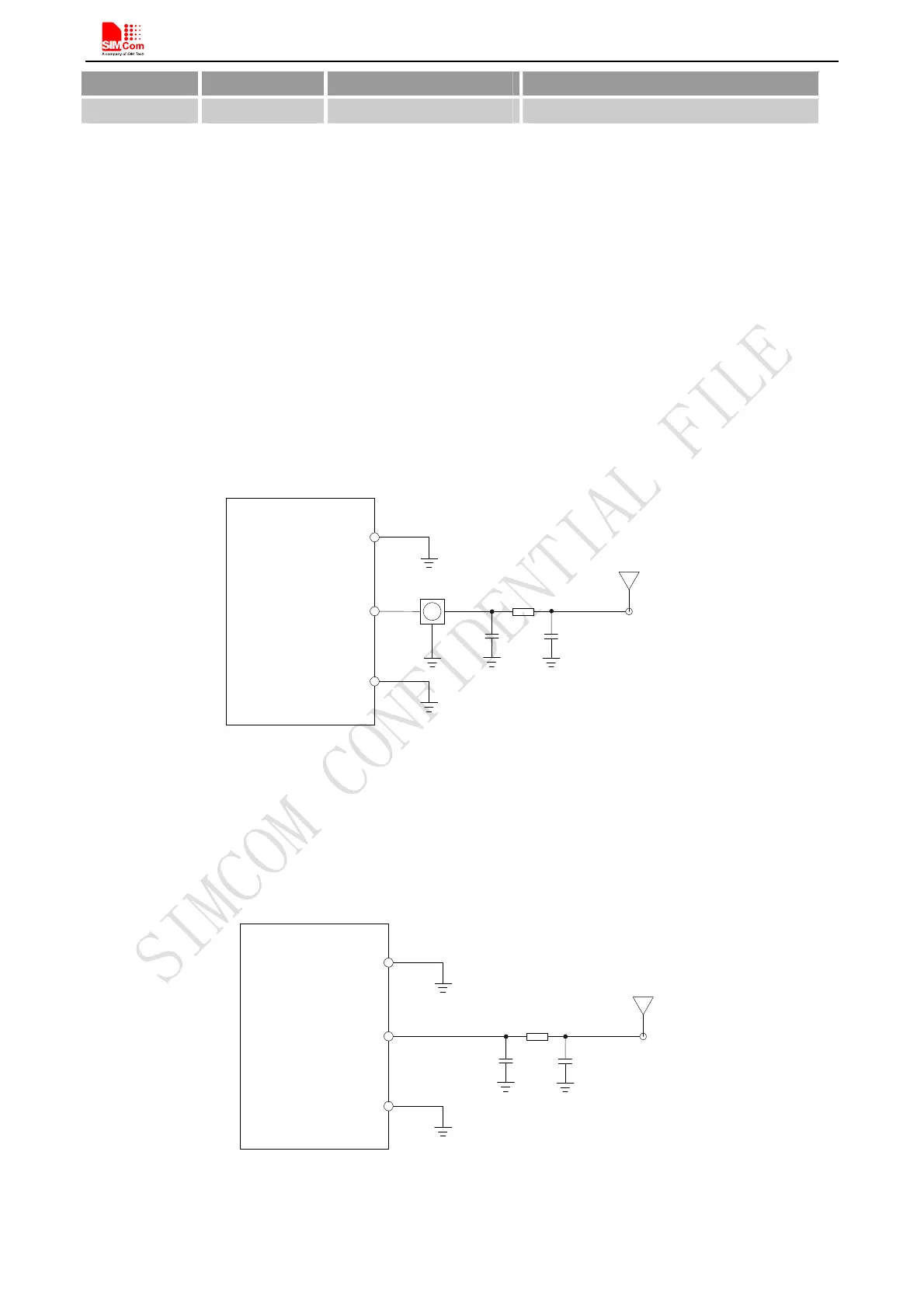
It is recommended to reserve the matching circuit as following:
Module
GND
(P in33)
R F connector
R101
GSM_ANT
C101
C102
GND
(P in31)
GSM
Antenna
(P in33)
Figure 36: GSM antenna matching circuit
R101,C101,C102 are the matching circuit, the value should be defined by the antenna design. Normally R101 is
0, C101 and C102 are not mounted.
The RF connector is used for conduction test. If the space between RF pin and antenna is not enough, the
matching circuit should be designed as in the following figure:
M odule
R101
GSM_ANT
C101
C102
GND
(P in33)
GND
(P in31)
GSM
Antenna
(P in33)
Figure 37: GSM antenna matching circuit without RF connector