Smart Machine Smart Decision
SIM800C_Hardware_Design_V1.02 30 2015-4-27
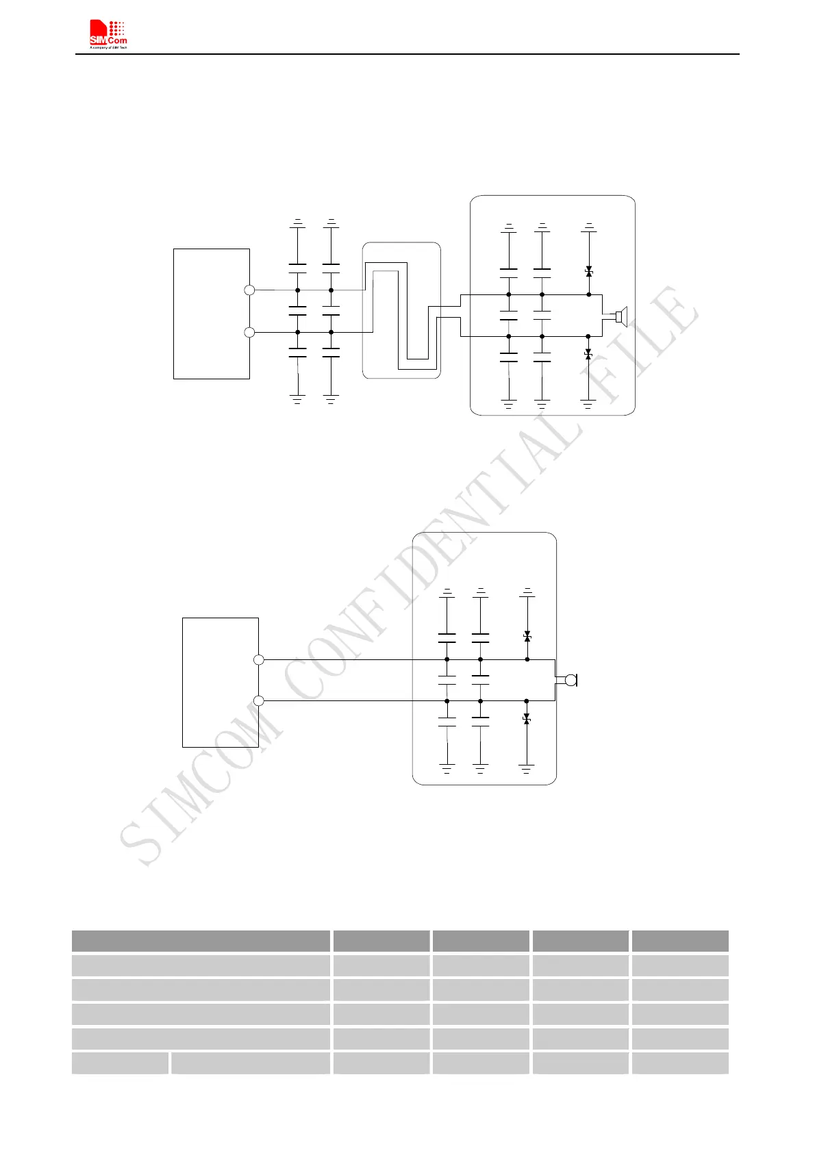
In order to improve audio performance, the following reference circuits are recommended. The audio signals
have to be layout according to differential signal layout rules as shown in following figures.
4.7.1. Speaker Interfaces Configuration
SPKP
Close to speaker
ESD
ESD
10pF
33pF
33pF
33pF
M odule
SPKN
10pF
10pF
10pF
33pF
33pF
33pF
10pF
10pF
Figure 28: Speaker reference circuit
4.7.2. Microphone Interfaces Configuration
Electret
Microphone
The lines in bold type should
be accorded to differential
signal layout rules
These components should
be placed to microphone
as close as possible
MICP
M odule
MICN
ESD
ESD
10pF
33pF
33pF
33pF
10pF
10pF
Figure 29: Microphone reference circuit
4.7.3. Audio Electronic Characteristic
Table 13: Microphone input characteristics
Parameter Min Typ Max Unit
Microphone biasing voltage - 1.9 2.2 V
Working current - - 2.0 mA
Input impedance(differential) 13 20 27 K
Idle channel noise - - -67 dBm0
SINAD Input level:-40dBm0 29 - - dB