Smart Machine Smart Decision
SIM800C_Hardware_Design_V1.02 24 2015-4-27
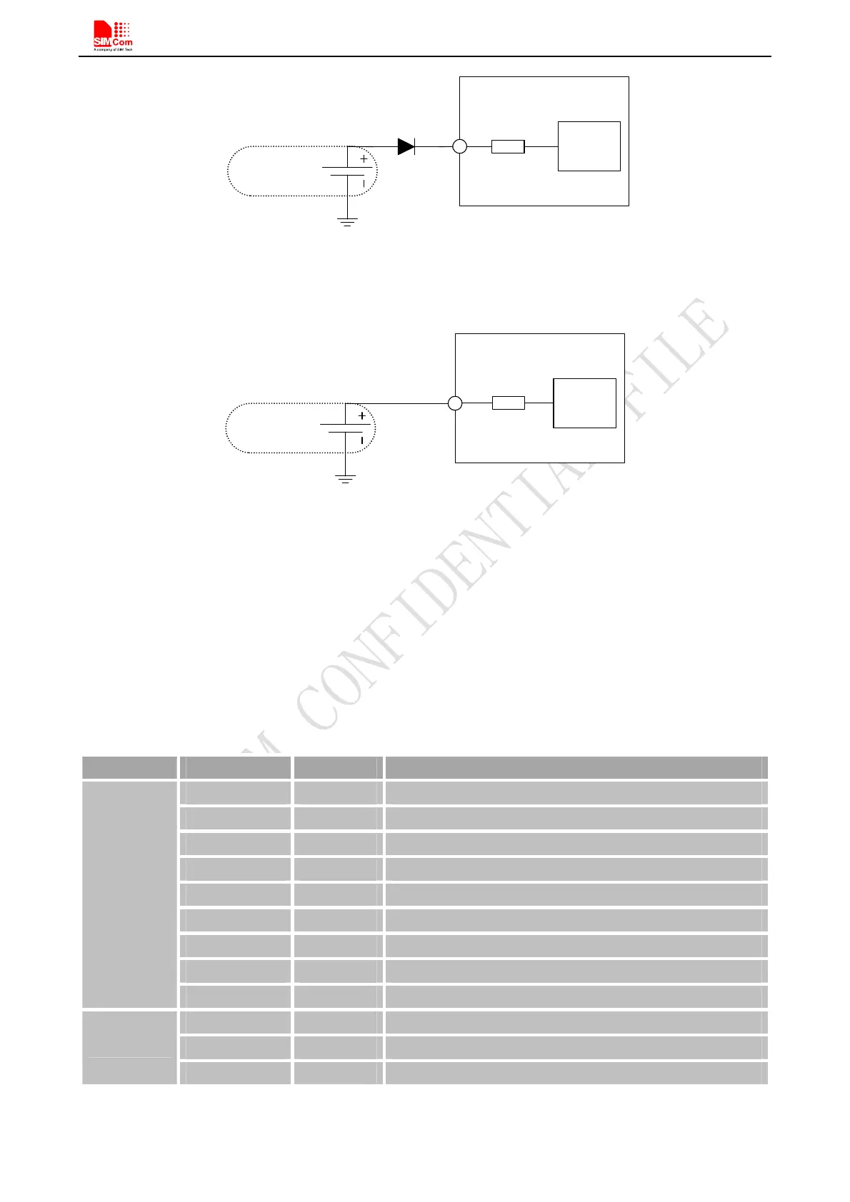
RTC
Core
1.5K
M odule
VRTC
N on-chargeable
B a c k u p B a tte ry
Figure 16: RTC supply from non-chargeable battery
Rechargeable battery backup
RTC
Core
1.5K
Module
VRTC
R echargeable
B a c k u p B a tte ry
Figure 17: RTC supply from rechargeable battery
Note: When shut off VBAT and power on VRTC only, the clock error becomes larger.
4.5. Serial Port and USB Interface
SIM800C default provides one unbalanced asynchronous serial ports. The module is designed as a DCE (Data
Communication Equipment). The following figure shows the connection between module and client (DTE).
Table 8: Serial port and USB pin definition
Note: Hardware flow control is disabled by default. AT command “AT+IFC=2, 2”can enable hardware flow
Pin name Pin number Function
UART1_DTR 6 Data terminal ready
UART1_RI 7 Ring indicator
UART1_DCD 5 Data carrier detect
UART1_CTS 4 Clear to send
UART1_RTS 3 Request to send
UART1_TXD 1 Transmit data
UART1_RXD 2 Receive data
UART2_TXD 22 Transmit data
Serial port
UART2_RXD 23 Receive data
USB_VBUS 24 USB power supply
USB_DP 25 D+ data input/output
Debug port
USB_DN 26 D- data input/output