Smart Machine Smart Decision
SIM800C_Hardware_Design_V1.02 39 2015-4-27
5. PCB Layout
This section will give some guidelines on PCB layout, in order to eliminate interfere or noise.
5.1 Pin Assignment
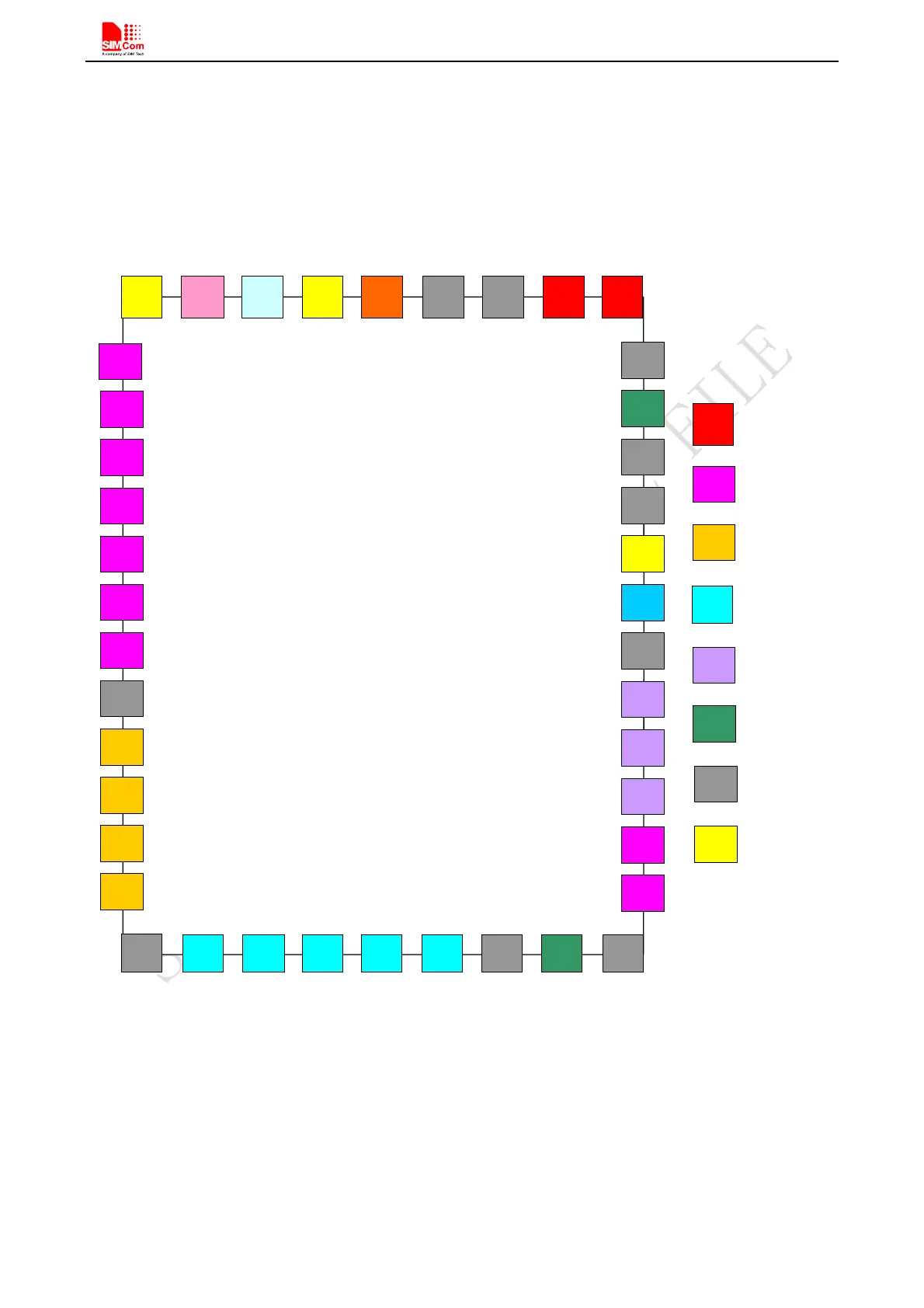
Before PCB layout, we should learn about pin assignment in order to get reasonable layout with so many
external components. Following figure is the overview of pin assignment of the module.
UART1_DTR
USB_DP
VBAT
VBAT
ADC
UART1_RXD
PWRKEY
UART1_CTS
UART1_TXD
UART1_RTS
UART1_DCD
NETLIGHT
SIM_RSTSIM_CLK
SIM_DET
SIM_DATA BT_ANT
UART2_TXD
SPKP
VRTC
MICP
MICN
USB_VBUS
USB_DM
GSM_ANT
STATUS
SIM_VDD
UART2_RXD
GND
13
SPKN
UART1_RI
14 15
16
21
17 18 19 20
22
23
24
25
26
27
28
29
30
31
32
33
37 36 35
34
1
42
41
40 39 38
5
4
2
3
6
11
10
9
8
7
12
VDD_EXT
GND
GND
GND
GND
GND
GND
GND
UART1_DTR
RF_SYNC
GND
GND
SIM800C
TOP VIEW
VBAT
UART
AUDIO
SIM CART
USB
ANTANA
GND
OTHERS
Figure 39: Pin assignment
5.2 Principle of PCB Layout
During layout, attention should be paid to the following interfaces, like Antenna, power supply, SIM card
interface, audio interface, and so on.