Smart Machine Smart Decision
SIM800C_Hardware_Design_V1.02 41 2015-4-27
6. Electrical, Reliability and Radio Characteristics
6.1 Absolute Maximum Ratings
The absolute maximum ratings stated in following table are stress ratings under non-operating conditions.
Stresses beyond any of these limits will cause permanent damage to SIM800C.
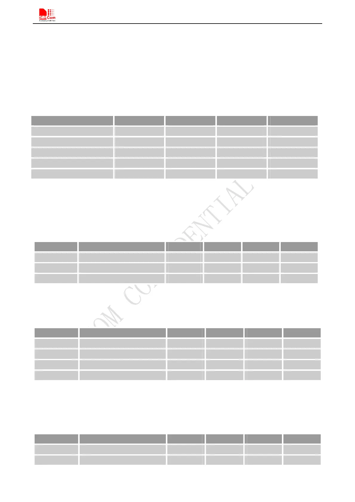
Table 27: Absolute maximum ratings
Symbol Min Typ Max Unit
VBAT - - 4.5 V
Current 0 - 2.0 A
USB_VBUS - - 12 V
I
I
* - 4 16 mA
I
O
* - 4 16 mA
*
These parameters are for digital interface pins, GPIO, and UART.
6.2 Recommended Operating Conditions
Table 28: Recommended operating conditions
Symbol Parameter Min Typ Max Unit
VBAT Power supply voltage 3.4 4.0 4.4 V
T
OPER
Operating temperature -40 +25 +85 ℃
T
STG
Storage temperature -45 +90 ℃
6.3 Digital Interface Characteristics
Table 29: Digital interface characteristics
Symbol Parameter Min Typ Max Unit
V
IH
High-level input current 2.1 - 3.1 V
V
IL
Low-level input current -0.3 - 0.7 V
V
OH
High-level output voltage 2.4 - - V
V
OL
Low-level output voltage - - 0.4 V
Note: These parameters are for digital interface pins, such as keypad, GPIO and UART.
6.4 SIM Card Interface Characteristics
Table 30: SIM card interface characteristics
Symbol Parameter Min Typ Max Unit
I
IH
High-level input current -1.0 - 1.0 uA
I
IL
Low-level input current -1.0 - 1.0 uA