Smart Machine Smart Decision
SIM800C_Hardware_Design_V1.02 26 2015-4-27
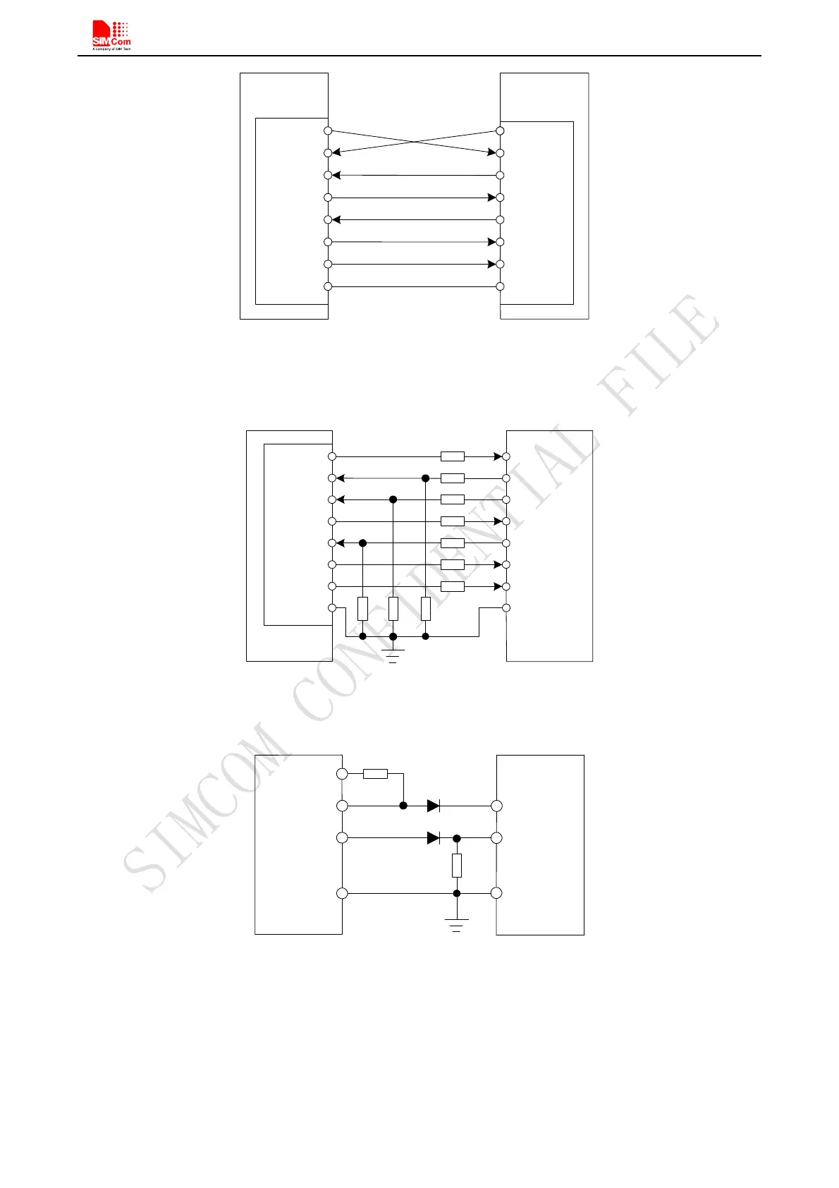
UART1_TXD
UART1_RXD
UART1_RTS
UART1_CTS
UART1_DTR
UART1_DCD
UART1_RI
TXD
RXD
RTS
CTS
DTR
DCD
RING
Serial P o rt
Serial P o rt
Module(D C E)
C ustom er(D TE )
GND GND
Figure 18: Connection of the serial interfaces
If the voltage of UART is 3.3V, the following reference circuits are recommended. If the voltage is 3.0V, please
change the resistors in the following figure from 5.6K to 14K.
1K
5.6K
RXD
TXD
RTS
CTS
GPIO
GPIO
EINT
DTE
(3 .3 V )
5.6K
5.6K
1K
1K
1K
1K
1K
1K
Module
UART1_TXD
UART1_RXD
UART1_RTS
UART1_CTS
UART1_DTR
UART1_DCD
UART1_RI
GND
GND
Figure 19: Resistor matching circuit
If the voltage of UART is 3V or3.3V, the following reference circuits are recommended:
UART1_TXD
RXD
M oduleDTE
TXDUART1_RXD
VDD_EXT
10K
10K
GND
GND
Figure 20 : Diode isolation circuit
Note: please make sure the minimum of client high limit should be less than 2.8V minus the diode drop.
If the voltage of UART is 5V, the following reference circuits are recommended: