33
Load loss accessory Ø 80 mm
Description Code
Load loss (mm H
2O)
Edea 30
Inlet Outlet
90° curve MF 8077450 0,25 0,30
45° curve MF 8077451 0,20 0,20
Horizontal extension W. 1000
mm
8077351 0,20 0,20
Vertical extension W. 1000
mm
8077351 0,20 0,20
Wall terminal 8089501 0,10 0,35
Roof outlet terminal (*) 8091204 1,10 0,15
Duct kit C(10)3
6296550 - -
6296543 - 1,8
Description Code
Load loss (mm H
2O)
Edea 40
Inlet Outlet
90° curve MF 8077450 0,30 0,4
45° curve MF 8077451 0,25 0,25
Horizontal extension W. 1000
mm
8077351 0,25 0,25
Vertical extension W. 1000
mm
8077351 0,25 0,25
Wall terminal 8089501 0,15 0,50
Roof outlet terminal (*) 8091204 1,5 0,2
Duct kit C(10)3 6296543 - 2,8
(*) The losses of the roof outlet terminal at inlet include the
manifold code 8091400.
NOTE:
for the boiler to operate correctly it is necessary that a
minimum distance of 0.50 m of the duct is respected with a
90° inlet curve.
6.12.6 Separate ducts (Ø 50 mm)
The
Edea
boiler is configured for use in Ø 50 mm discharge
flues. To ensure correct boiler operation, parameter PAR31
(long flues) should be set on the basis of the length of the in-
stalled flues, as indicated in the table.
PAR 31
Edea 30
Ø 50 mm outlet Discharge diaphragm
0 1 x 90° elbow + 2 metres leave it mounted
0 1 x 90° elbow + 6 metres remove
2 1 x 90° elbow + 10 metres remove
4 1 x 90° elbow + 14 metres remove
6 1 x 90° elbow + 18 metres remove
8 1 x 90° elbow + 22 metres remove
10 - -
12 - -
PAR 31
Edea 40
Ø 50 mm outlet Discharge diaphragm
0 1 x 90° elbow + 12 metres remove
2 - -
4 - -
6 - -
8 - -
NOTE:
to remove the discharge diaphragm, proceed as illus-
trated in “Fig. 26”.
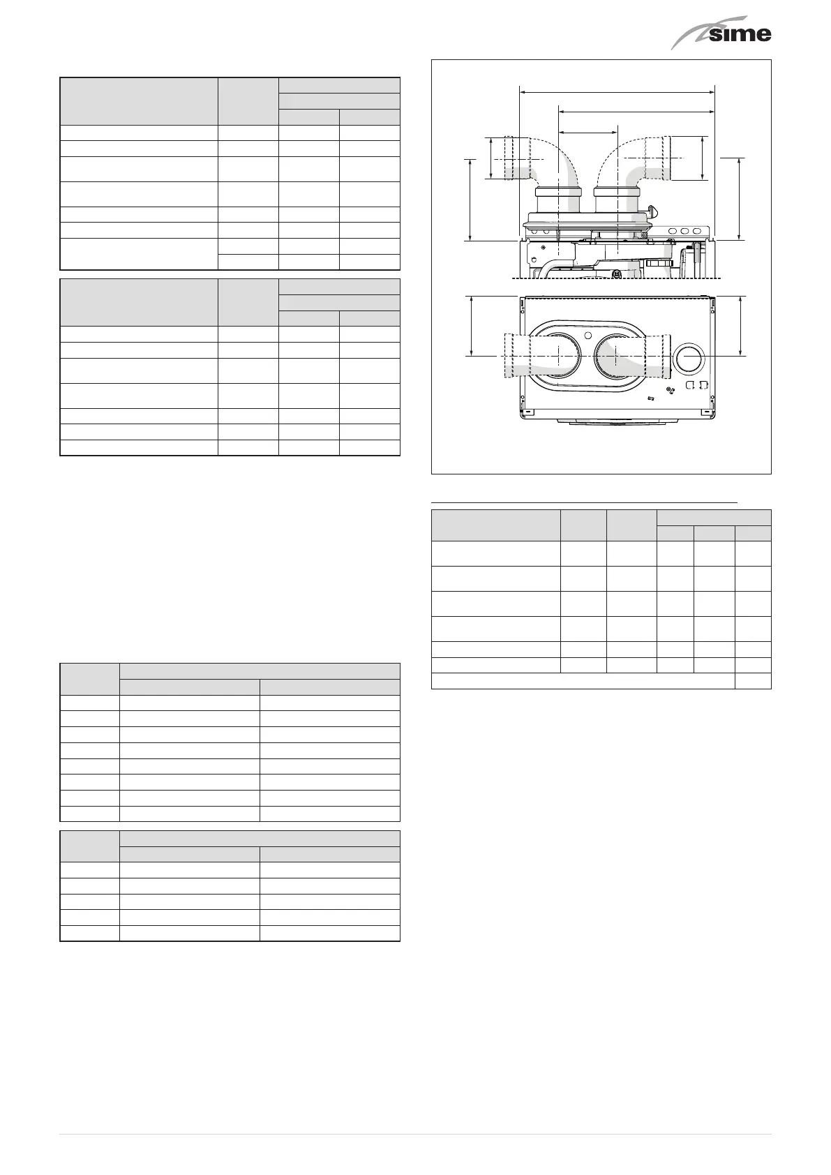
120
Ø 80
170
Ø 80
320
125
Fig. 28
Example: calculation of the load loss of a
Edea 30
boiler.
Accessories Ø 80 mm
Code
Quantity
Load loss (mm H2O)
Inlet
Outlet
Total
Extension W. 1000 mm
(horizontal)
8077351
9
9 x
0,20
- 1,80
Extension W. 1000 mm
(horizontal)
8077351
9 -
9 x
0,20
1,80
90° curve
8077450
2
2 x
0,25
- 0,50
90° curve
8077450
2 -
2 x
0,30
0,60
Wall terminal
8089501
1 0,10 - 0,10
Wall terminal
8089501
1 - 0,35 0,35
TOTAL 5,15
(installation permitted since the total of the load loss of the
accessories used is less than 15 mmH
2O).