36
d
IT IS FORBIDDEN
To use water pipes for earthing the appliance.
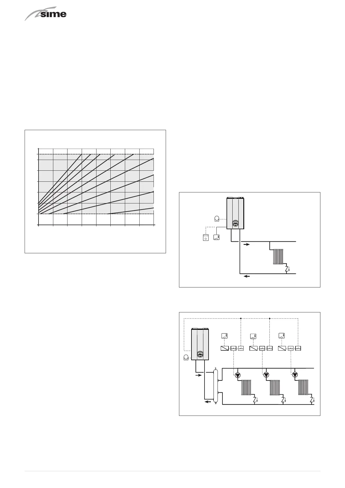
6.13.1 External temperature sensor
The boiler is prearranged for connection to an external air
temperature sensor and can operate with a sliding temper-
ature.
This means that the delivery temperature sent to the boiler
can vary on the basis of the external temperature depending
on the climatic curve selected from those shown in the dia-
gram (Fig. 35).
When fitting the sensor on the outside of the building, follow
the instructions provided on the packaging of the product it-
self.
Climatic curve
Delivery temperature
20 15 10 5 0 -10 -15-5 -20
80
90
70
60
50
40
30
20
K=9 K=7K=8 K=5K=6
K=3
K=4
K=2
K=1
External temperature
Fig. 35
m
CAUTION
If there is an external sensor, turn the heating knob
t
until the required curve K has been selected with-
in the range
K=0.0 - K=9.0
in order to select the opti-
mal climatic curve for the system and therefore the
delivery temperature based on the external temper-
ature.
m
CAUTION
The adjustment of the Maximum Heating Tempera-
ture is managed by
"PAR 14"
(see paragraph "List of
parameters").
6.13.2 Chrono-thermostat or Air Thermostat
The electrical connection of the chrono-thermostat or air
thermostat has already been described. When fitting the com-
ponent in the room where the readings are to be taken, follow
the instructions provided on the packaging of the product it-
self.
6.13.3 EXAMPLE of use of the command/control
device on some types of heating systems
KEY
M System delivery
R System return
CR Remote control
EXP Expansion card
SE External temperature sensor
TA Air thermostat for boiler activation
TZ1÷TZ3 Air thermostat for the zone
VZ1-VZ3 Zone valves
RL1-RL3 Zone relays
P1-P3 Zone pump
SP Hydraulic separator
IP Floor system
VM Thermostatic mixer valve
TSB Low temperature safety thermostat
ONE DIRECT ZONE system , external sensor and air thermo-
stat.
R
M
SE
TA
Fig. 36
MULTI ZONE system - with pump, air thermostat and exter-
nal sensor.
TA
TZ2
TZ3
TZ1
P3
RL1
SP
RL2 RL3
P2P1
R
M
Fig. 37