35
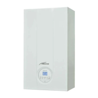
To facilitate introduction of the connection wires of the option-
al components into the boiler:
– remove the screws (1), pull the front panel (2) forwards and
release it from the top by lifting it
2
Fig. 31
– remove the screws (3) securing the control panel (4)
– move the panel (4) upwards (a) but keeping it in the side
guides (5) to the end of travel
– bring it forwards and down (b) until it is horizontal
3
a
b
5
4
Fig. 32
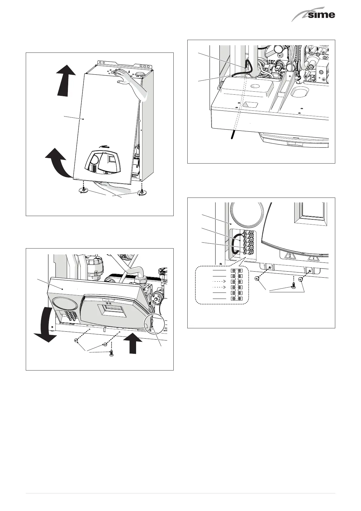
– insert the connection wires into the cable gland (6) and the
opening (7) on the control panel
6
7
Fig. 33
– bring the control panel (4) to the original position and se-
cure it with the screws (3) which were removed previously
– connect the component wires to the terminal board (8) fol-
lowing the indications provided on the data plate (9).
3
4
8
9
SE
TA1
SR
6
5
4
3
2
1
Fig. 34
m
CAUTION
It is compulsory:
– to use an omnipolar cut-off switch, disconnect
switch, in compliance with EN standards (contact
opening of at least 3 mm)
– if the power cable is to be replaced, that ONLY a
special cable is used with a factory produced re-
wired connector, ordered as a spare part and con-
nected by a professionally qualified person
– to connect the earth wire to an effective earthing
system (*)
– that before any intervention on the boiler, the
mains power is disconnected by setting the main
system switch to "OFF".
(*) The manufacturer is not responsible for any damage
caused by failure to earth the appliance or failure to ob-
serve the information provided in the wiring diagrams.