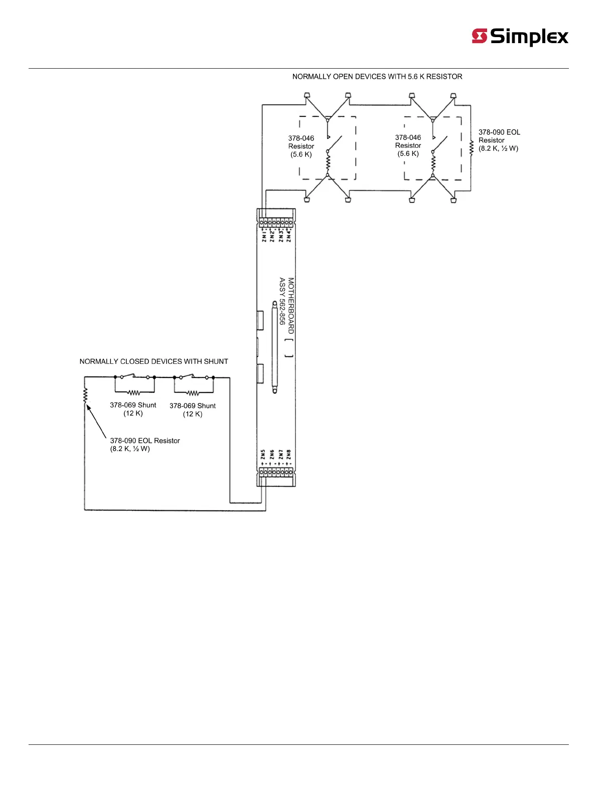
Figure 25: 4100-5004 / 4120-5004 or 4100-5005 Security Wiring (2)
• Wiring is 18 AWG minimum, or to local code.
• Conductors must test free of all grounds.
• If a zone is not used, connect an 8.2 K, 1/2 W resistor (378-090) across zone terminals.
• Each zone is marked with its circuit number. Refer to the 4100 Programmer Report, which references the exact wires connected.
• Connect devices to the appropriate zone. The zone shown in the figure is an example.
• Maximum of 5 N.C. devices with a 12 K shunt.
• Maximum of 5 N.O. devices with a 5.6 K resistor.
• For zones that connect to contacts only, the maximum line resistance is 800 Ohms.
579-205 Rev. H
© 2020 Johnson Controls. All rights reserved. All specifications and other information shown were current as of document revision and are subject to change without notice. Additional listings may be applicable, contact your local Autocall
product supplier for the latest status. Listings and approvals under Tyco Fire & Security GmbH, and the product names listed in this material are marks and/or registered marks. Unauthorized use is strictly prohibited. NFPA 72 and National
Fire Alarm Code are registered trademarks of the National Fire Protection Association (NFPA).