3-8
FigureTag FD4-709-09
2979-8904
-COMM
+COMM
-COMM
+COMM
-COMM
+COMM
-COMM
+COMM
6979-,9879-8904
BLUE
WHITE
WHITE
BLUE
1979-8904
+
-
BLUE
WHITE
teNDI/IITENPAM+
teNDI/IITENPAM-
BLACK/WHITE
BLACK
V42+
V0
V42+
V0
MORF
LENAP
SECIVEDV42REHTOOT
REHTOOT
/IITENPAM
SECIVEDteNDI
)2ETONEES(
ESABROSNESESABROSNES ESABROSNES
.O.N
R
E
TNEC
.C.N
NEERG
E
G
NARO
7379-8902
YALER
EES(
)9ETON
KCALB
KCALB
EUL
B
TELOIV
YERG
WOLLEY
RETNEC
.C.N
.O.N
2289-8904
YALER
ELUDOM
EULB
ETIHW
DER
DER
KCALB
KCALB
NWORB
T
EL
O
I
V
YERG
.O.N
RETNEC
.C.N
BTCATNOC
)4ETONEES(
EGNARO
W
OLLEY
NEERG
RETNEC
.C.N
.O.N
ATCATNOC
)4ETONEES(
EES(
)5ETON
EES(
)6ETON
EES(
)9ETON
+
-
80
89
-
89
02
DELETOMER
2289-8904RO
)DESUFI(YALER
)1ETONEES(
+
-
TXENOT
CANROV42
TIUCRIC
+24V OR NAC +ALM
0V OR NAC -ALM
MORF
LENAP
BTCATNOC
)7ETONEES(
ATCATNOC
)7ETONEES(
3979-8904
ESABROSNES
)8ETONES(
REHTOOT
ECIVEDTENDI
)2ETONEES(
EES(
)6ETON
5979-,4979-8904
+S
+
-
-S
MORF
LENAP
teNDI/IITENPAM+
teNDI/IITENPAM-
DLEIHS
)3ETONEES(
DLEIHS
)3ETONEES(
DLEIHS
)3ETONEES(
DLEIHS
)3ETONEES(
-9797 , -979 8
)01&8SETONEES(
MORF
0104
LENAP
L
A
NO
I
TPOSI
D
L
E
IHS
)3ETONEES(
DLEIHS
COMM
COMM
COMM
COMM
teNDI
teNDI
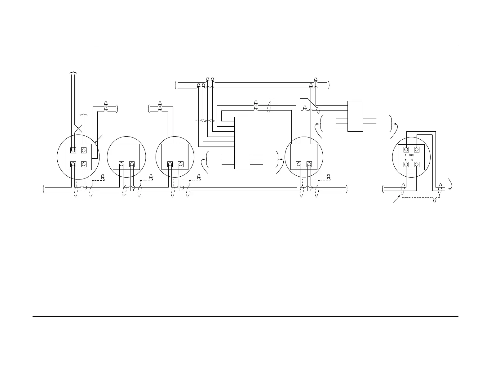
-73erugiF moke/Heat Sensor Base ConnectionsS
Notes:
1. Remote LED and relay wires are not supervised.
2. Maximum quantity of devices per circuit is 127 for 4020, 4100+, 4100U/4100ES (MAPNET), or 4120, 128 for the 2120 CDT panel, 200 for the 4008 panel, and 250 for the 4010 and
4100U/4100ES (IDNET) panel. Maximum quantity of 4098-9795 -9796 and -9797 Multi-Sensor bases is 63 with 4020, 4100+, 4100U,
4100ES and 4120, 100 for 4008 panel, and 124
for the 4010 panel. If the sounder output is coded (Temporal code, etc.) via MAPNET II/IDNet control see Note 10.
3. If shield is used, twist shield wires together and cap with wire nut. Shield should be insulated from electrical box.
4. Contact A or B: Dry, Form C - each rated 2 amperes at 24 VDC/0.5 amperes at 110 VAC, resistive.
5. 18 to 32 VDC, .008 amperes typical/.013 amperes max.
6. Do not use remote LED if the 4098-9822 relay module is used.
7. Contact A or B: Dry, Form C – Each rated at 3 amperes at 28 VDC/115 VAC, resistive.
8. Remove the protective tape over the CO Sensor on the 4098-9797 and -9798 bases only after the sensor head has been installed.
9. Maximum wire length between 4098-9791 sensor base and 2098-9737 relay module is 100 feet.
10. Maximum quantity of sensors with 4098-9794, -9795, and -9798 sounder bases limited to 43 if output is coded (Temporal code, etc.) via MAPNET II/IDNet control.
If coding is performed via 24VDC or NAC circuit, see Note 2.
Continued on next page
4098 TrueAlarm Sensor Bases,
Continued
Wiring