3-7
The 4098-9795 and 4098-9796 Multi-Sensor Bases are only
for use with the 4098-9754
multi-sensor and are not compatible with the 2120 CDT. Both bases have remote LED output and
the 4098-9795 also has an integrated sounder similar to the 4098-9794 Sounder Base. The
4098-9795 and 4098-9796 Multi-Sensor Bases must be used with the 4098-9754 multi-sensor
when connected to a 4010, 4020, 4100+, 4008, or 4120 system. When connected to a 4100U or a
4100ES the 4098-9754 multi-sensor can also be used with the 4098-9789, -9791, -9792, -9793, -
9794, -9797, and -9798 bases.
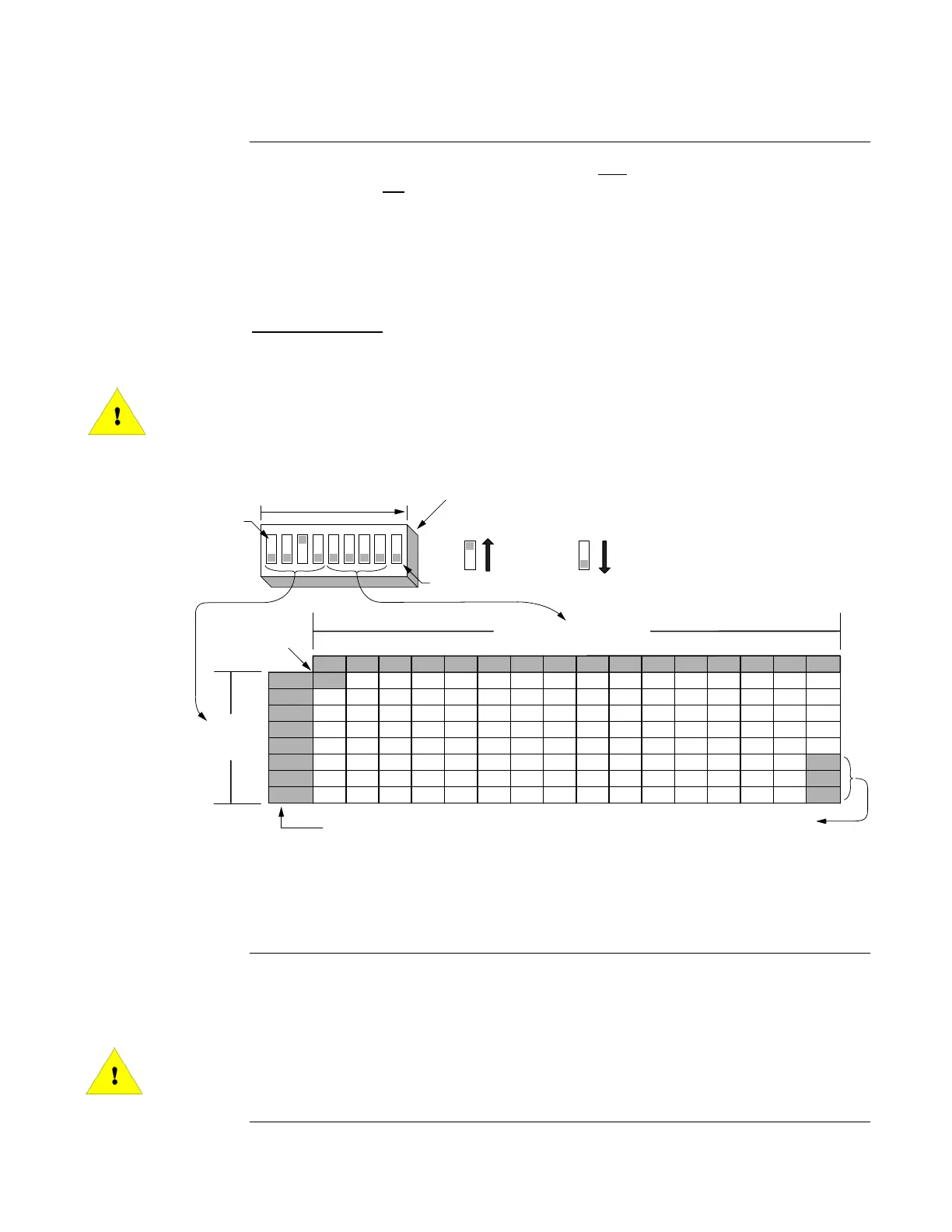
The Multi-Sensor Base answers to two addresses, therefore the DIP Switch must be set for
even addresses only
. The even address is a photo sensor/sounder base (4098-9795) or a photo
sensor/standard base (4098-9796), and the odd address (DIP Switch + 1) is a heat sensor/standard
base. The figure below shows the allowable addresses for the Multi-Sensor Bases.
IMPORTANT: Switch Position 1 is not used and must always be OFF (0) for the
Multi-Sensor Bases to function properly. The odd address immediately
after the DIP Switch setting must not be used by any other sensor base or
MAPNET/IDNet device.
0000 1000 0100 1100 0010 1010 0110 1110 0001 1001 0101 1101 0011 1011 0111 1111
0000
0 16 32 48 64 80 96 112 128 144 160 176 192 208 224 240
0100
2 18 34 50 66 82 98 114 130 146 162 178 194 210 226 242
0010
4 20 36 52 68 84 100 116 132 148 164 180 196 212 228 244
0110
6 22 38 54 70 86 102 118 134 150 166 182 198 214 230 246
0001
8 24 40 56 72 88 104 120 136 152 168 184 200 216 232 248
0101
10 26 42 58 74 90 106 122 138 154 170 186 202 218 234 250
0011
12 28 44 60 76 92 108 124 140 156 172 188 204 220 236
0111
14 30 46 62 78 94 110 126 142 158 174 190 206 222 238
LSB MSB
1 23456789
DIP SWITCHES 5 THRU 8
SWITCH 1 MUST BE SET TO OFF
FOR PROPER OPERATION
RESERVED FOR FUTURE USE
RESERVED FOR
FUTURE USE
DIP
SWITCHES
1 THRU 4
ON
OFF
1 = ON 0 = OFF
252
254
DIPSWITCH IS SHOWN
SET AT ADDRESS 4.
SEE
NOTE 1
SEE
NOTE
Figure 3-6. 4098-9795, -9796, 9798 Multi-Sensor Base DIP Switch Address Settings
Note: The 4098-9795 Multi-Sensor Sounder Base has a 9-position DIP Switch that is used for
setting base address and selecting the sounder power source. See Figure 3-2 for DIP Switch
location.
Sensor bases are connected to the fire alarm control panel via a single wire pair for the 4098-9789,
-9792, -9793, -9796, and -9797 and two pairs of wires for the 4098-9791, -9794, -9795, and -9798.
Using Figure 3-7 as a reference, connect the bases to the MAPNET II/IDNet wire pair and 24V
power
(if used).
IMPORTANT: For additions to existing installations, remove power from the panel
before wiring any bases to avoid damage to equipment.
Continued on next page
4098 TrueAlarm Sensor Bases,
Continued
Multi-Sensor Bases
4098-9795 and
4098-9796
Wiring