2-10
All screw terminals accommodate 14 to 18 AWG solid or stranded wire. When tightening
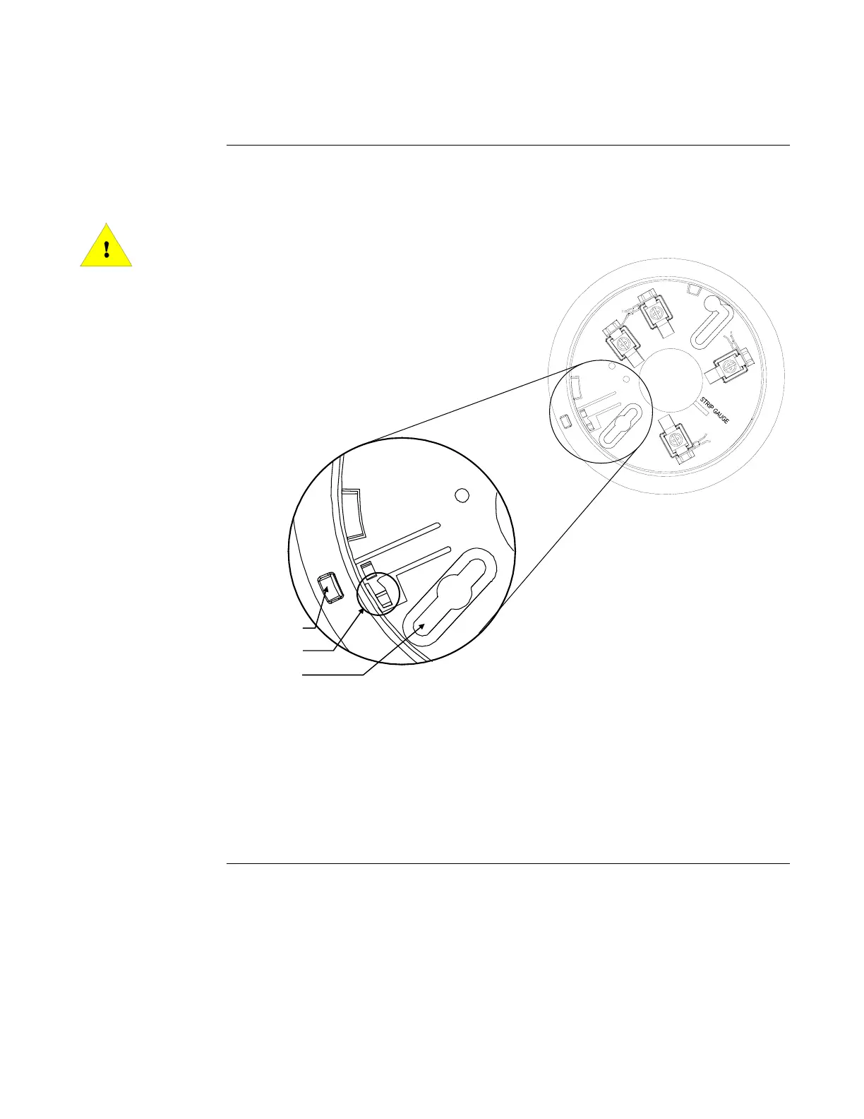
screws, the range of torque is 8 to 12 in-lbs. Connect wiring to the terminals shown in the figure
below. (Figures 2-2 through 2-6 show typical wiring applications for the 4098 bases.)
CAUTION: Do not loop wire under terminals. Break wire run to provide
supervision of connections.
2
1
3
4
Figure 2-2. Wiring and Mounting the Bases
FigureTag FD4-709-03
Notes:
1. Break off plastic tab where indicated to engage locking mechanism.
2. Once locking mechanism is engaged, you must insert a flat-head screwdriver in slot
indicated to release the detector from the base.
3. Use the slotted hole indicated for the first screw when mounting the base.
Continued on next page
4098 Bases,
Continued
Wiring
See Note 2
See Note 1
See Note 3