EasyManuals Logo

Simplex 4098-9614 Applications Manual

Simplex 4098-9614
64 pages
To Next Page IconTo Next Page
To Previous Page IconTo Previous Page
Page #39 background imageLoading...
Page #39 background image
3-9
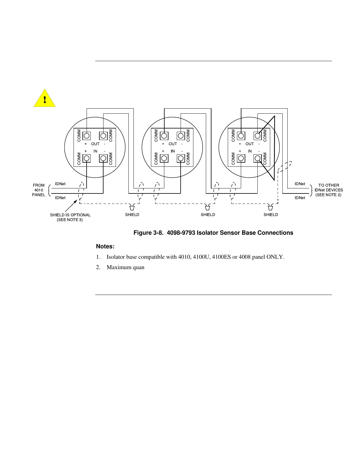
Figure 3-8 shows the wiring connections for the isolator sensor base. All screw terminals accept
14 to 18-gauge AWG solid or stranded. Maximum torque should not exceed 12-inch-pounds.
CAUTION: Do not loop wire under terminals. Break wire runs to provide
supervision.



  
  













 

 
 
  



Figure 3-8. 4098-9793 Isolator Sensor Base Connections
Notes:
1. Isolator base compatible with 4010, 4100U, 4100ES or 4008 panel ONLY.
2. Maximum quantity of devices per circuit is 250 for 4010, 4100U and 4100ES panels.
3. If shield is used, twist shield wires together and cap with wire nut. Shield should be insulated
from electrical box.
4098 TrueAlarm Sensor Bases,
Continued
Wiring
firealarmresources.com

Table of Contents

Other manuals for Simplex 4098-9614

Questions and Answers:

Question and Answer IconNeed help?

Do you have a question about the Simplex 4098-9614 and is the answer not in the manual?

Simplex 4098-9614 Specifications

General IconGeneral
BrandSimplex
Model4098-9614
CategoryFire Alarms
LanguageEnglish

Related product manuals