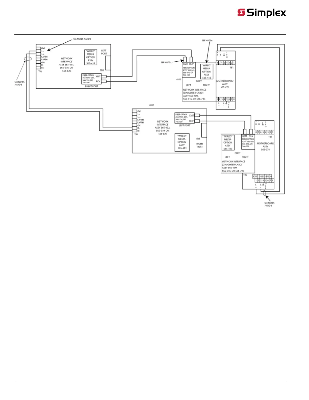
Figure 27: Wired and dual fiber-optic media, Class X wiring (0746-109 only)
Notes:
1. Refer to general wiring precautions in this document. For specific information about fiber-optic wiring, refer to the 900-143 Fiber Tutorial.
2. The available communications distance is determined by the properties of the specific fiber cable used and the available power budget. The
maximum distance between nodes is determined by the total loss from the transmitter to the associated receiver, for example, fiber loss,
connector loss, splice loss, and safety margin) or the maximum distance listed, whichever is smaller. See Table 1 for allowed losses.
3. ST connectors with long strain relief boots are to be used with the fiber-optic cable.
4. On assembly 565-274, JW1 and JW2 must be installed. Jumper plugs must not be installed on P5-P8.
5. Cable clamps supplied with 748-531 are used to secure the fiber cable.
6. When the 565-413 Interface Card is used with 566-793, 565-516, -407, or –409 Network Card, TB1 on the 565-413 Interface Card cannot be used.
Connection to the motherboard is required as shown.
7. The shield should only be connected at one end of the line. The shield is connected to the left port.
8. Each “wired” media cable requires two ferrite beads, one at each end (included in the shipping group). Refer to installation instructions 574-041
for proper bead mounting.
Duplex fiber-optic Class X wiring (0566-1197, 0566-1198, 0566-1199, 0566-1200 only)
page 27 579-182 Rev. V
4100/4120-6014, 4100-6078 NICs and 4100/4120-Series Media Modules Installation Instruction