18 — Operang Instrucons
number and enter the new
value on the numeric keypad
that appears (see Figure 24
on page 17). Enter the
desired value and press the
↵ button to return to the
previous screen, or press
“E” to return to the main
screen without changing the
value.
In the lower right quadrant of the screen is the KW Jog
value. is indicates by how many kilowatts you will increase
or decrease the load by pressing the “-” and “+” buttons,
respectively. To change this value, press the number and enter
your choice using the numeric keypad.
To begin testing, press the “Master Load” button. is will
activate the load bank and begin applying the load displayed
in the upper right area of the screen. To quickly decrease or
increase the load, press the “-” and “+” buttons.
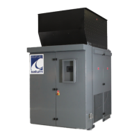
If you have purchased the
metering upgrade, pressing
the F3 function key or “F3 -
Information” on the screen
while the test is running will
bring up the metering screen
(see Figure 26). Here you can
monitor the voltage, current,
load applied to the source,
and the frequency of the electricity. is screen also displays the
temperatures registered by the load bank’s three sensors.
If any of three voltage or current values are signicantly dierent
from the other two, check the load bank for a blown fuse. If no
blown fuse is found, contact Simplex service at 800-637-8603, ext. 4.
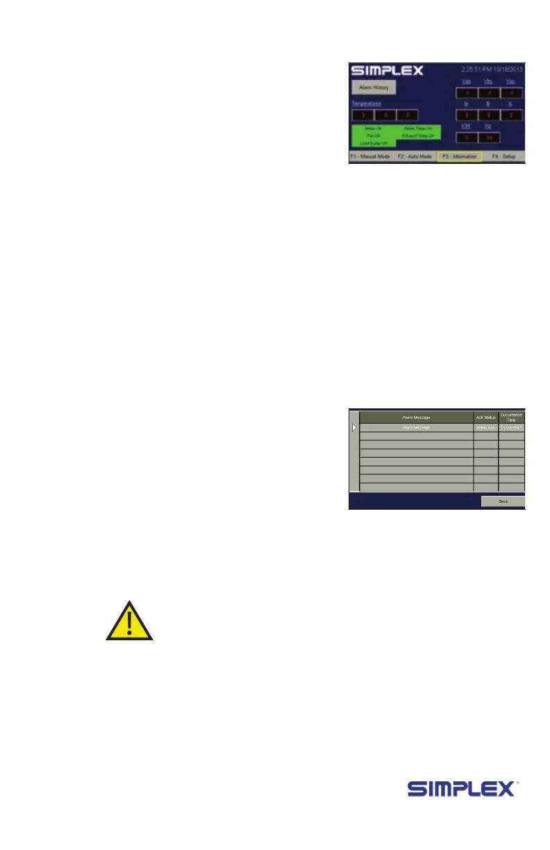
Pressing “Alarm History” on this screen will bring up a list of
registered alarms (See Figure 27.)
When the test is complete, press the Master Load button then
the Control Power button to remove the load from the test source.
e load bank’s fan will continue running for the duration of the
cooldown delay (see page 16 for more information).
teSting
operation
metering (if
equipped)
SHutdown and
Cooling
Figure 24 HMI
Information
Figure 25 Alarm History