2-13
A
Use the following procedure when mounting a TrueAlert Addressable Controller.
CAUTION: Read all instructions carefully before cutting conduit/service entrances
and installing back box. Failure to comply with all installation
requirements may result in a violation of UL or FCC regulations.
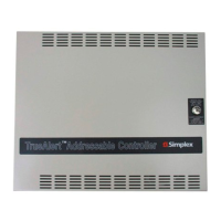
1. Lay the TrueAlert Addressable Controller on a flat surface.
2. Unlock and open the panel door. Disconnect the AC wiring harness from the card cage.
Remove the electronic card cage assembly and store it in a safe, dry area.
3. Determine the amount and proper location of conduit/service entrances (see Figure 2-5).
Make all appropriate entrances into the back box. Power limited and non-power limited
wiring must enter through separate conduit/service entrances. AC power entrance into the
back box is recommended at the bottom right side of the back box.
Note: Maximum intrusion into back box for conduit is ½ inch (1.27 cm).
Recommended Conduit Locations
Locate conduit entry approximately where shown.
A. Class B or Class A Fiber Feed and AC Power
B. Signaling Line Circuits, IDNet and RUI
C. IDNet, RUI, or Class A Fiber Return
D. SLCs, NACs, IDNet, and RUI or Class A Fiber Return
E. Control Inputs: IDNet, RUI, or Notification Appliance Circuits
Figure 2-6. Installing the 4009 Back Box
Continued on next page
System Installation, Continued
Mounting the 4009
TrueAlert
Addressable
Controller
B
BATTERY
MOUNTING
AREA (NO
CONDUIT
ENTRY)
KNOCKOUT
SCREW/NAIL
HOLES for
SEMI-FLUSH
MOUNTING
TOP VIEW
NON-POWER LIMITED WIRING ONLY
C
D
E
A
 Loading...