Landlord / 1700 / 2700 Series
TP 300-2226-02-LL-SMA
1/200110
Lubrication continued…
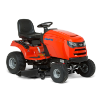
Figure 18. Mower Lubrication Points
Figure 17. Arbor Lubrication Points
Lubricate Rear Axle Shafts
NOTE: This section has been included for reference pur-
poses only. It does not need to be performed as part of
new unit setup.
We recommend removing the rear wheel hubs and lubri-
cating the axle shafts yearly. This prevents the wheel
hubs from seizing onto the axle shafts and makes future
service easier.
1. Turn off the ignition, turn off the PTO, engage the
parking brake, and block the front tires.
2. Using a jack or chain hoist positioned at the center of
the rear frame, carefully jack the unit up until the rear
tires are approximately 1"- 2" off the ground.
NOTE: For overall unit stability during service, do not
jack rear end higher than required for wheel removal.
3. Support the rear of the unit on jackstands positioned
under the rear frame.
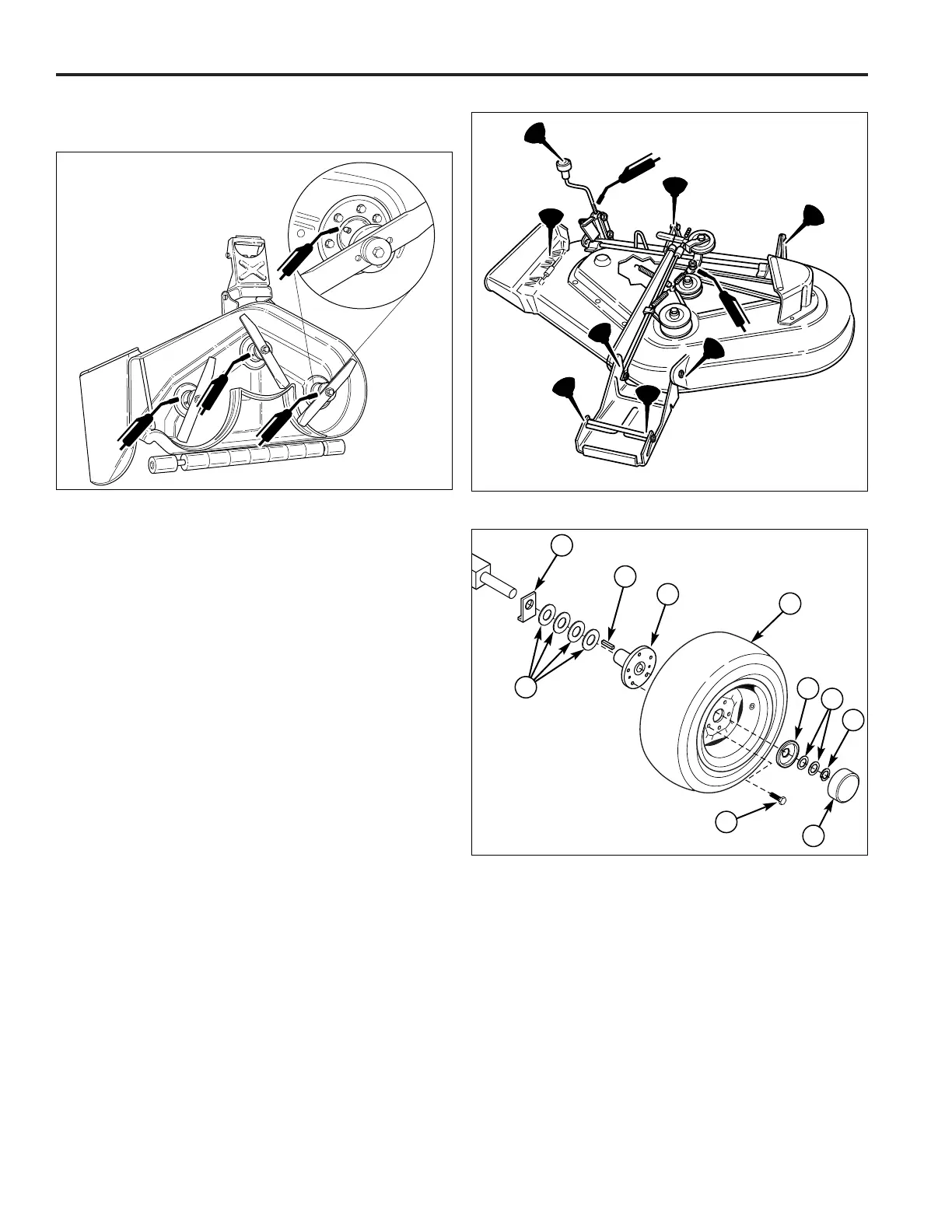
NOTE: Your axle assembly may differ slightly from the
assembly pictured: the quantity of washers (G, Figure
19) may be one or two. This is adjusted on a tractor by
tractor basis during assembly to allow a small amount of
axle end-play.
4. Remove the wheel bolts (J, Figure 19) and wheels
(E).
5. Remove the plastic hub cap (I).
6. Remove E-ring (H) using a screwdriver.
7. Remove the washers (G), hub cap retainer (F), and
wheel hub (D). Remove the key (C).
8. Lubricate the axle shaft with anti-seize compound or
lithium grease.
9. Reinstall the components in reverse order of disas-
sembly and lower the unit. Be sure the key (C) is in
place in the axle keyway.
A
B
C
D
E
F
G
H
I
J
Figure 19. Rear Axle Assembly
A. Anti-Rotation Washer G. Small Washers
B. Large Washers (As Required)
C. Key H. E-Ring
D. Wheel Hub I. Hub Cap
E. Wheel & Tire Assy. J. Capscrew
F. Hub Cap Retainer