Landlord / 1700 / 2700 Series
TP 300-2226-02-LL-SMA
1/200118
Electric PTO Clutch
Adjustment
Check the PTO clutch adjustment after the initial 50 hour
break-in period and then after every 250 hours of opera-
tion. Also perform the following procedure if the clutch is
slipping or will not engage.
1. Remove key from ignition switch and disconnect
spark plug wires to prevent the possibility of acciden-
tal starting while the PTO is being adjusted.
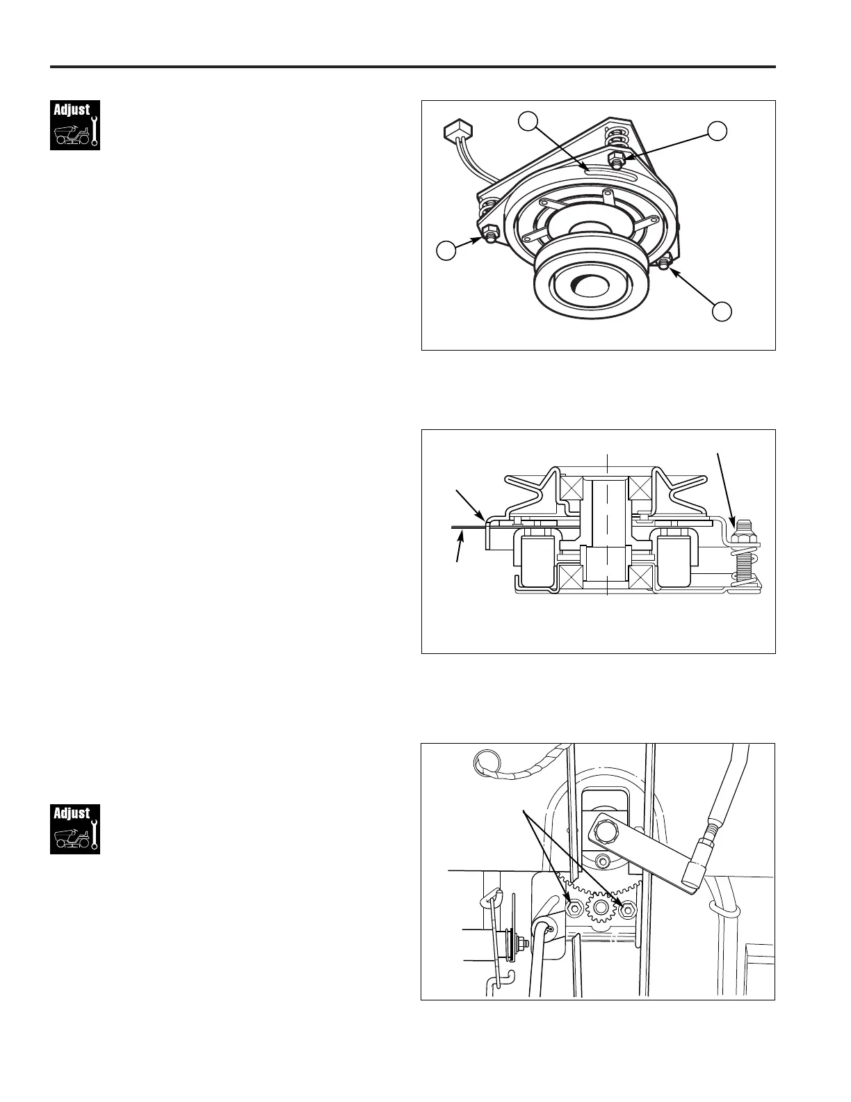
2. See Figure 33. Note the position of the 3 adjustment
windows (A) in the side of the brake plate and the
nylock adjustment nuts (B).
3. Insert a .012” feeler gauge through each window,
positioning the gauge between the rotor face and the
armature face as shown in Figure 34.
4. Alternately tighten the adjustment nuts (B, Figure 33)
until the rotor face and armature face just contacts the
gauge.
5. Check the windows for an equal amount of tension
when the gauge is inserted and removed, and make
any necessary adjustments by tightening or loosening
the adjustment nuts.
NOTE: The actual air gap between the rotor and arma-
ture may vary even after performing the adjustment pro-
cedure. This is due to dimensional variations on compo-
nent parts, and is an acceptable condition.
6. Check the mower blade stopping time. The mower
blades and mower drive belt should come to a com-
plete stop within five seconds after the electric PTO
switch is turned off (see MOWER BLADE STOPPING
CHECK, Page 16).
Figure 33. PTO Clutch Adjustment
A. Adjustment Window (Qty. 3, one shown)
B. Adjustment Nuts
Window
Adjustment
Nut
Figure 34. Feeler Gauge Position
.012”
Feeler
Gauge
(3) Req’d
Steering Gear
Adjustment
If there is excessive slack in the steering system, the steering
gear can be moved closer to the steering shaft gear.
1. Loosen the two nuts (Figure 35)
2. Push the bracket so that the gear teeth are closely
meshed.
3. Retighten the nuts after adjustment.
A
B
B
B
Figure 35. Steering Gear Adjustment
Nuts